Nissan Altima (L32) 2007-2012 Service Manual: P0725 engine speed signal
Description
The engine speed signal is sent from the ECM to the TCM by CAN communication line.
DTC Logic
DTC DETECTION LOGIC
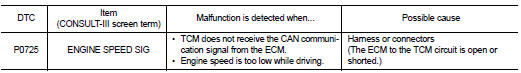
DTC CONFIRMATION PROCEDURE
CAUTION: Always drive vehicle at a safe speed.
NOTE: If “DTC CONFIRMATION PROCEDURE” has been previously performed, always turn ignition switch OFF.
Then wait at least 10 seconds before performing the next test.
1.CHECK DTC DETECTION

1. Turn ignition switch ON.
2. Select “DATA MONITOR”.
3. Start engine and maintain the following conditions for at least 10 consecutive seconds.
PRI SPEED SEN : More than 1000 rpm
Is “P0725 ENGINE SPEED SIG” detected? YES >> Go to TM-142, "Diagnosis Procedure".
NO >> Check intermittent incident. Refer to GI-42, "Intermittent Incident".
Diagnosis Procedure
1.CHECK DTC WITH ECM

1. Turn ignition switch ON.
2. Perform “SELF-DIAG RESULTS” mode for “ENGINE”.
Is the inspection result normal? YES >> GO TO 2.
NO >> Check DTC detected item. Refer to EC-1555, "DTC Index".
2.CHECK DTC WITH TCM

Perform “SELF-DIAG RESULTS” mode for “TRANSMISSION”.
Is “P0725 ENGINE SPEED SIG” detected? YES >> Replace TCM. Refer to TM-254, "Exploded View".
NO >> GO TO 3.
3.DETECT MALFUNCTIONING ITEMS
Check TCM connector pin terminals for damage or loose connection with harness connector.
Is the inspection result normal? YES >> Replace TCM. Refer to TM-254, "Exploded View".
NO >> Repair or replace damaged parts.
 P0720 vehicle speed sensor cvt (secondary
speed sensor)
P0720 vehicle speed sensor cvt (secondary
speed sensor) P0730 belt damage