Nissan Altima (L32) 2007-2012 Service Manual: P0744 a/t tcc s/v function (lock -up)
Description
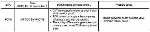
This malfunction is detected when the torque converter clutch does not lock-up as instructed by the TCM. This is not only caused by electrical malfunction (circuits open or shorted), but also by mechanical malfunction such as control valve sticking, improper solenoid valve operation, etc.
DTC Logic
DTC DETECTION LOGIC
DTC CONFIRMATION PROCEDURE
CAUTION: Always drive vehicle at a safe speed.
NOTE: If “DTC CONFIRMATION PROCEDURE” has been previously performed, always turn ignition switch OFF.
Then wait at least 10 seconds before performing the next test.
1.CHECK DTC DETECTION

1. Turn ignition switch ON.
2. Select “DATA MONITOR”.
3. Start engine and maintain the following condition for at least 30 seconds.
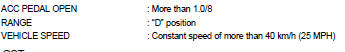

Follow the procedure “With CONSULT-III”.
Is “P0744 A/T TCC S/V FNCTN” detected? YES >> Go to TM-146, "Diagnosis Procedure".
NO >> Check intermittent incident. Refer to GI-42, "Intermittent Incident".
Diagnosis Procedure
1.CHECK LINE PRESSURE
Perform line pressure test. Refer to TM-247, "Inspection and Judgment".
Is the inspection result normal? YES >> GO TO 2.
NO >> Repair or replace damaged parts. Refer to TM-247, "Inspection and Judgment".
2.CHECK TORQUE CONVERTER CLUTCH SOLENOID VALVE
1. Turn ignition switch OFF.
2. Disconnect CVT unit harness connector.
3. Check torque converter clutch solenoid valve. Refer to TM-147, "Component Inspection (Torque Converter Clutch Solenoid Valve)".
Is the inspection result normal?
YES >> GO TO 3.
NO >> Replace transaxle assembly. Refer to TM-259, "Exploded View".
3.CHECK LOCK-UP SELECT SOLENOID VALVE
Check lock-up select solenoid valve. Refer to TM-147, "Component Inspection (Lock-up Select Solenoid Valve)".
Is the inspection result normal? YES >> GO TO 4.
NO >> Replace transaxle assembly. Refer to TM-259, "Exploded View".
4.CHECK OUTPUT SPEED SENSOR (SECONDARY SPEED SENSOR) SYSTEM
Check output speed sensor (secondary speed sensor) system. Refer to TM-146, "DTC Logic".
Is the inspection result normal? YES >> GO TO 5.
NO >> Repair or replace damaged parts.
5.CHECK INPUT SPEED SENSOR (PRIMARY SPEED SENSOR) SYSTEM
Check input speed sensor (primary speed sensor) system. Refer to TM-135, "DTC Logic".
Is the inspection result normal? YES >> GO TO 6.
NO >> Repair or replace damaged parts.
6.DETECT MALFUNCTIONING ITEMS
Check TCM connector pin terminals for damage or loose connection with harness connector.
Is the inspection result normal? YES >> Replace TCM. Refer to TM-254, "Exploded View".
NO >> Repair or replace damaged parts.
Component Inspection (Torque Converter Clutch Solenoid Valve)
1.CHECK TORQUE CONVERTER CLUTCH SOLENOID VALVE
Check resistance between CVT unit terminal 12 and ground.
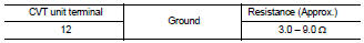
Is the inspection result normal? YES >> INSPECTION END
NO >> Replace transaxle assembly. Refer to TM-259, "Exploded View".
Component Inspection (Lock-up Select Solenoid Valve)
1.CHECK LOCK-UP SELECT SOLENOID VALVE
Check resistance between CVT unit connector terminal and ground.
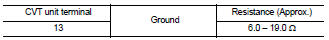
Is the inspection result normal? YES >> INSPECTION END
NO >> Replace transaxle assembly. Refer to TM-259, "Exploded View".
 P0740 torque converter clutch solenoid
valve
P0740 torque converter clutch solenoid
valve P0745 line pressure solenoid valve