Nissan Altima (L32) 2007-2012 Service Manual: P1212 TCS Communication line
Description
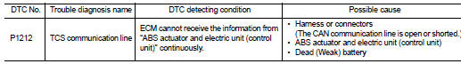
This CAN communication line is used to control the smooth engine operation during the TCS operation. Pulse signals are exchanged between ECM and “ABS actuator and electric unit (control unit)”.
Be sure to erase the malfunction information such as DTC not only for “ABS actuator and electric unit (control unit)” but also for ECM after TCS related repair.
DTC Logic
DTC DETECTION LOGIC
NOTE: • If DTC P1212 is displayed with DTC UXXXX, first perform the trouble diagnosis for DTC UXXXX.
Refer to EC-1179, "DTC Logic".
• If DTC P1212 is displayed with DTC P0607, first perform the trouble diagnosis for DTC P0607. Refer to EC-1378, "DTC Logic".
Freeze frame data is not stored in the ECM for this self-diagnosis.
DTC CONFIRMATION PROCEDURE
1.PRECONDITIONING
If DTC Confirmation Procedure has been previously conducted, always perform the following before conducting the next test 1. Turn ignition switch OFF and wait at least 10 seconds.
2. Turn ignition switch ON.
3. Turn ignition switch OFF and wait at least 10 seconds.
TESTING CONDITION: Before performing the following procedure, confirm that battery voltage is more than 10.5 V at idle.
>> GO TO 2.
2.PERFORM DTC CONFIRMATION PROCEDURE
1. Start engine and let it idle for at least 10 seconds.
2. Check 1st trip DTC.
Is 1st trip DTC detected? YES >> Go to EC-1387, "Diagnosis Procedure".
NO >> INSPECTION END
Diagnosis Procedure
Go to BRC-6, "Work Flow".
 P1148, P1168 Closed loop control
 P1217 Engine over temperature