Nissan Altima (L32) 2007-2012 Service Manual: P1217 Engine over temperature
DTC Logic
DTC DETECTION LOGIC
NOTE: • If DTC P1217 is displayed with DTC UXXXX, first perform the trouble diagnosis for DTC UXXXX.
Refer to EC-1179, "DTC Logic".
• If DTC P1217 is displayed with DTC P0607, first perform the trouble diagnosis for DTC P0607. Refer to EC-1378, "DTC Logic".
If the cooling fan or another component in the cooling system malfunctions, engine coolant temperature will rise.
When the engine coolant temperature reaches an abnormally high temperature condition, a malfunction is indicated.
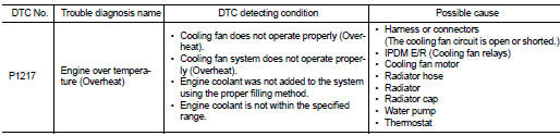
CAUTION: When a malfunction is indicated, always replace the coolant. Refer to CO-34, "System Inspection".
Also, replace the engine oil. Refer to LU-23, "Inspection".
1. Fill radiator with coolant up to specified level with a filling speed of 2 liters per minute. Always use coolant with the proper mixture ratio. Refer to MA-12, "Fluids and Lubricants".
2. After refilling coolant, run engine to ensure that no water-flow noise is emitted.
DTC CONFIRMATION PROCEDURE
1.PERFORM COMPONENT FUNCTION CHECK
Perform component function check. Refer to EC-1388, "Component Function Check".
NOTE: Use component function check to check the overall function of the cooling fan. During this check, a DTC might not be confirmed.
Is the inspection result normal? YES >> INSPECTION END
NO >> Go to EC-1389, "Diagnosis Procedure".
Component Function Check
1.PERFORM COMPONENT FUNCTION CHECK-I
WARNING: Never remove the radiator cap when the engine is hot. Serious burns could be caused by high pressure fluid escaping from the radiator.
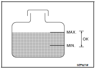
Wrap a thick cloth around cap. Carefully remove the cap by turning it a quarter turn to allow built-up pressure to escape. Then turn the cap all the way off.
Check the coolant level in the reservoir tank and radiator.
Allow engine to cool before checking coolant level.
Is the coolant level in the reservoir tank and/or radiator below the proper range? YES >> Go to EC-1389, "Diagnosis Procedure".
NO >> GO TO 2.
2.PERFORM COMPONENT FUNCTION CHECK-II
Confirm whether customer filled the coolant or not.
Did customer fill the coolant? YES >> Go to EC-1389, "Diagnosis Procedure".
NO >> GO TO 3.
3.PERFORM COMPONENT FUNCTION CHECK-III

1. Turn ignition switch ON.
2. Perform “COOLING FAN” in “ACTIVE TEST” mode with CONSULT-III.
3. Check that cooling fan motors-1 and -2 operate at each speed (LOW/MID/HI).

Perform IPDM E/R auto active test and check cooling fan motors operation, refer to PCS-14, "Diagnosis Description".
Is the inspection result normal? YES >> INSPECTION END
NO >> Go to EC-1389, "Diagnosis Procedure".
Diagnosis Procedure
1.CHECK COOLING FAN OPERATION

1. Turn ignition switch ON.
2. Perform “COOLING FAN” in “ACTIVE TEST” mode with CONSULT-III.
3. Check that cooling fans-1 and -2 operate at each speed (LOW/MID/HI).

1. Perform IPDM E/R auto active test and check cooling fan motors operation, refer to PCS-14, "Diagnosis Description".
2. Check that cooling fans-1 and -2 operate at each speed (Low/Middle/High).
Is the inspection result normal? YES >> GO TO 2.
NO >> Go to EC-1473, "Diagnosis Procedure".
2.CHECK COOLING SYSTEM FOR LEAKAGE-I
Check cooling system for leakage. Refer to CO-34, "System Inspection".
Is leakage detected? YES >> GO TO 3.
NO >> GO TO 4.
3.CHECK COOLING SYSTEM FOR LEAKAGE-II
Check the following for leakage.
• Hose
• Radiator
• Water pump
>> Repair or replace malfunctioning part.
4.CHECK RADIATOR CAP
Check radiator cap. Refer to CO-34, "System Inspection".
Is the inspection result normal? YES >> GO TO 5.
NO >> Replace radiator cap.
5.CHECK THERMOSTAT
Check thermostat. Refer to CO-46, "Removal and Installation".
Is the inspection result normal? YES >> GO TO 6.
NO >> Replace thermostat
6.CHECK ENGINE COOLANT TEMPERATURE SENSOR
Refer to EC-1211, "Component Inspection".
Is the inspection result normal? YES >> GO TO 7.
NO >> Replace engine coolant temperature sensor.
7.CHECK MAIN 12 CAUSES
If the cause cannot be isolated, check the following.
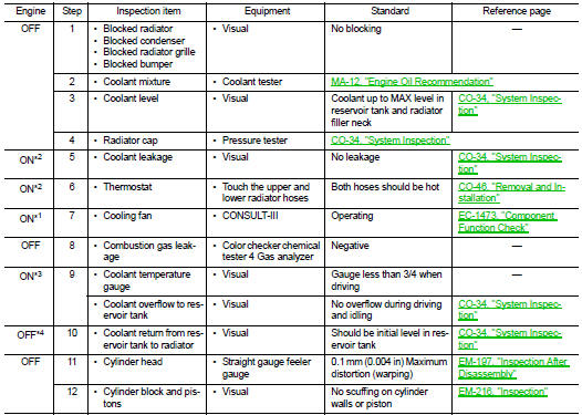
*1: Turn the ignition switch ON.
*2: Engine running at 3,000 rpm for 10 minutes.
*3: Drive at 90 km/h (56 MPH) for 30 minutes and then let idle for 10 minutes.
*4: After 60 minutes of cool down time.
For more information, refer to CO-32, "Troubleshooting Chart".
>> INSPECTION END
 P1212 TCS Communication line
 P1225 TP Sensor