Nissan Altima (L32) 2007-2012 Service Manual: P1554 Battery current sensor
Description
The power generation voltage variable control enables fuel consumption to be decreased by reducing the engine load which is caused by the power generation of the generator. The battery current sensor is installed to the battery cable at the negative terminal. The sensor measures the charging/discharging current of the battery.
Based on the sensor signal, ECM judges whether or not the power generation voltage variable control is performed. When performing the power generation voltage variable control, ECM calculates the target power generation voltage based on the sensor signal. And ECM sends the calculated value as the power generation command value to IPDM E/R. For the details of the power generation voltage variable control, refer to CHG-6, "System Description".
CAUTION: Never connect the electrical component or the ground wire directly to the battery terminal. The connection causes the malfunction of the power generation voltage variable control, and then the battery discharge may occur.
DTC Logic
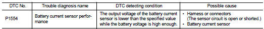
DTC DETECTION LOGIC
NOTE: If DTC P1554 is displayed with DTC P0643, first perform the trouble diagnosis for DTC P0643. Refer to EC-1379, "DTC Logic".
DTC CONFIRMATION PROCEDURE
1.PERFORM COMPONENT FUNCTION CHECK
Perform component function check. Refer to EC-1407, "Component Function Check".
NOTE: Use component function check to check the overall function of the battery current sensor circuit. During this check, a 1st trip DTC might not be confirmed.
Is the inspection result normal? YES >> INSPECTION END
NO >> Go to EC-1408, "Diagnosis Procedure".
Component Function Check
1.PRECONDITIONING
TESTING CONDITION: • Before performing the following procedure, confirm that battery voltage is more than 12.8 V at idle.
• Before performing the following procedure, confirm that all load switches and A/C switch are turned OFF.
>> GO TO 2.
2.PERFORM COMPONENT FUNCTION CHECK

1. Start engine and let it idle.
2. Select “BAT CUR SEN” in “DATA MONITOR” mode with CONSULT-III.
3. Check “BAT CUR SEN” indication for 10 seconds.
“BAT CUR SEN” should be above 2,300 mV at least once.

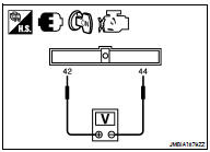
1. Start engine and let it idle.
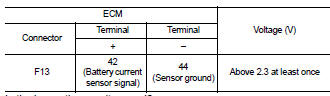
2. Check voltage between ECM harness connector terminals under the following conditions.
Is the inspection result normal? YES >> INSPECTION END
NO >> Go to EC-1408, "Diagnosis Procedure"
Diagnosis Procedure
1.CHECK GROUND CONNECTION
1. Turn ignition switch OFF.
2. Check ground connection E9. Refer to Ground Inspection in GI-45, "Circuit Inspection".
Is the inspection result normal? YES >> GO TO 2.
NO >> Repair or replace ground connection.
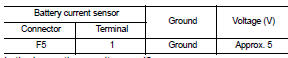
2.CHECK BATTERY CURRENT SENSOR POWER SUPPLY CIRCUIT
1. Disconnect battery current sensor harness connector.
2. Turn ignition switch ON.
3. Check the voltage between battery current sensor harness connector and ground.
Is the inspection result normal? YES >> GO TO 3.
NO >> Repair open circuit, short to ground or short to power in harness or connectors.
3.CHECK BATTERY CURRENT SENSOR GROUND CIRCUIT FOR OPEN AND SHORT
1. Turn ignition switch OFF.
2. Disconnect ECM harness connector.
3. Check the continuity between battery current sensor harness connector and ECM harness connector.
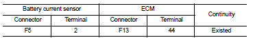
4. Also check harness for short to ground and short to power.
Is the inspection result normal? YES >> GO TO 4.
NO >> Repair open circuit, short to ground or short to power in harness or connectors.
4.CHECK BATTERY CURRENT SENSOR INPUT SIGNAL CIRCUIT FOR OPEN AND SHORT
1. Check the continuity between battery current sensor harness connector and ECM harness connector.
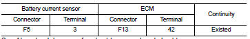
2. Also check harness for short to ground and short to power.
Is the inspection result normal? YES >> GO TO 5.
NO >> Repair open circuit, short to ground or short to power in harness or connectors.
5.CHECK BATTERY CURRENT SENSOR
Refer to EC-1405, "Component Inspection".
Is the inspection result normal? YES >> GO TO 6.
NO >> Replace battery negative cable assembly.
6.CHECK INTERMITTENT INCIDENT
Refer to GI-42, "Intermittent Incident".
>> INSPECTION END
Component Inspection
1.CHECK BATTERY CURRENT SENSOR
1. Turn ignition switch OFF.
2. Reconnect harness connectors disconnected.
3. Disconnect battery negative cable (1).

4. Install jumper cable (A) between battery negative terminal and body ground.
5. Turn ignition switch ON.
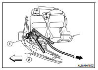
6. Check the voltage between ECM harness connector terminals under the following conditions.
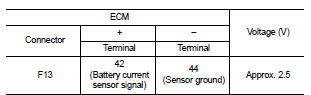
Before measuring the terminal voltage, confirm that the battery is fully charged.
Refer to PG-3, "How to Handle Battery".
Is the inspection result normal? YES >> INSPECTION END
NO >> Replace battery negative cable assembly.
 P1553 Battery current sensor
 P1564 ASCD Steering switch