Nissan Altima (L32) 2007-2012 Service Manual: P1564 ASCD Steering switch
Description
ASCD steering switch has variant values of electrical resistance for each button. ECM reads voltage variation of switch, and determines which button is operated.
Refer to EC-1090, "System Diagram" for the ASCD function.
DTC Logic
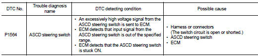
DTC DETECTION LOGIC
NOTE: If DTC P1564 is displayed with DTC P0605, first perform the trouble diagnosis for DTC P0605. Refer to EC-1376, "DTC Logic".
DTC CONFIRMATION PROCEDURE
1.PRECONDITIONING
If DTC Confirmation Procedure has been previously conducted, always perform the following before conducting the next test.
1. Turn ignition switch OFF and wait at least 10 seconds.
2. Turn ignition switch ON.
3. Turn ignition switch OFF and wait at least 10 seconds.
>> GO TO 2.
2.PERFORM DTC CONFIRMATION PROCEDURE
1. Turn ignition switch ON and wait at least 10 seconds.
2. Press MAIN switch for at least 10 seconds, then release it and wait at least 10 seconds.
3. Press CANCEL switch for at least 10 seconds, then release it and wait at least 10 seconds.
4. Press RESUME/ACCELERATE switch for at least 10 seconds, then release it and wait at least 10 seconds.
5. Press SET/COAST switch for at least 10 seconds, then release it and wait at least 10 seconds.
6. Check DTC.
Is DTC detected? YES >> Go to EC-1410, "Diagnosis Procedure".
NO >> INSPECTION END
Diagnosis Procedure
1.CHECK GROUND CONNECTION
1. Turn ignition switch OFF.
2. Check ground connection E9. Refer to Ground Inspection in GI-45, "Circuit Inspection".
Is the inspection result normal? YES >> GO TO 2.
NO >> Repair or replace ground connection.
2.CHECK ASCD STEERING SWITCH CIRCUIT

1. Turn ignition switch ON.
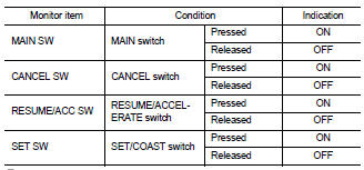
2. Select “MAIN SW”, “CANCEL SW”, “RESUME/ACC SW” and “SET SW” in “DATA MONITOR” mode with CONSULT-III.
3. Check each item indication under the following conditions.

1. Turn ignition switch ON.
2. Check the voltage between ECM harness connector terminals under the following conditions.
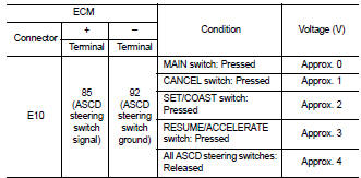
Is the inspection result normal? YES >> GO TO 8.
NO >> GO TO 3.
3.CHECK ASCD STEERING SWITCH GROUND CIRCUIT FOR OPEN AND SHORT
1. Turn ignition switch OFF.
2. Disconnect ECM harness connector.
3. Disconnect combination switch harness connector.
4. Check the continuity between combination switch and ECM harness connector.
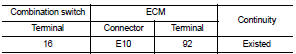
5. Also check harness for short to ground and short to power.
Is the inspection result normal? YES >> GO TO 5.
NO >> GO TO 4.
4.DETECT MALFUNCTIONING PART
Check the following.
• Harness connectors E30, M1
• Combination switch (spiral cable)
• Harness for open and short between ECM and combination switch
>> Repair open circuit, short to ground or short to power in harness or connectors.
5.CHECK ASCD STEERING SWITCH INPUT SIGNAL CIRCUIT FOR OPEN AND SHORT
1. Check the continuity between combination switch and ECM harness connector.
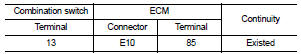
2. Also check harness for short to ground and short to power.
Is the inspection result normal? YES >> GO TO 7.
NO >> GO TO 6.
6.DETECT MALFUNCTIONING PART
Check the following.
• Harness connectors E30, M1
• Combination switch (spiral cable)
• Harness for open and short between ECM and combination switch
>> Repair open circuit, short to ground or short to power in harness or connectors.
7.CHECK ASCD STEERING SWITCH
Refer to EC-1412, "Component Inspection".
Is the inspection result normal? YES >> GO TO 8.
NO >> Replace ASCD steering switch.
8.CHECK INTERMITTENT INCIDENT
Refer to GI-42, "Intermittent Incident".
>> INSPECTION END
Component Inspection
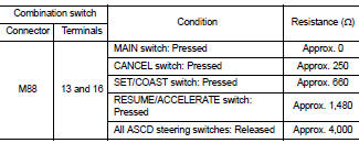
1.CHECK ASCD STEERING SWITCH
1. Turn ignition switch OFF.
2. Disconnect combination switch (spiral cable) harness connector.
3. Check resistance between combination switch harness connector terminals as per the following.
Is the inspection result normal? YES >> INSPECTION END
NO >> Replace ASCD steering switch
 P1554 Battery current sensor
 P1572 ASCD Brake switch