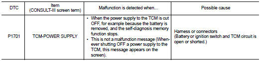
Nissan Altima (L32) 2007-2012 Service Manual: P1701 transmission control module (power supply)
Description
When the power supply to the TCM is cut OFF, for example because the battery is removed, and the self-diagnosis memory function stops, malfunction is detected.
NOTE: Since “P1701 TCM-POWER SUPPLY” will be indicated when replacing TCM, perform diagnosis after erasing “SELF-DIAG RESULTS”
DTC Logic
DTC DETECTION LOGIC
DTC CONFIRMATION PROCEDURE
NOTE: If “DTC CONFIRMATION PROCEDURE” has been previously performed, always turn ignition switch OFF.
Then wait at least 10 seconds before performing the next test.
1.CHECK DTC DETECTION

1. Turn ignition switch ON.
2. Wait for at least 2 consecutive seconds.
3. Perform “SELF-DIAG RESULTS” mode for “TRANSMISSION”.
Is “P1701 TCM-POWER SUPPLY” detected? YES >> Go to TM-172, "Diagnosis Procedure".
NO >> Check intermittent incident. Refer to GI-42, "Intermittent Incident".
Diagnosis Procedure
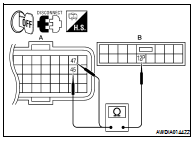
1.CHECK TCM POWER SOURCE
1. Turn ignition switch OFF.
2. Disconnect TCM harness connector.
3. Turn ignition switch ON.
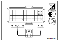
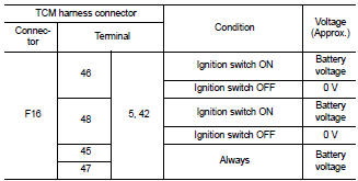
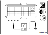
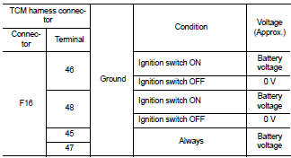
4. Check voltage between TCM harness connector F16 terminal 46, 48, 45, 47 and 5, 42.
Is the inspection result normal? YES >> GO TO 6.
NO >> GO TO 2.
2.CHECK TCM GROUND CIRCUIT
1. Turn ignition switch OFF.
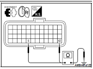
2. Check continuity between TCM harness connector F16 terminal 5, 42 and ground.
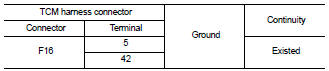
Is the inspection result normal? YES >> GO TO 3.
NO >> Repair or replace damaged parts.
3.CHECK TCM POWER CIRCUIT
1. Turn ignition switch ON.
2. Check voltage between TCM harness connector F16 terminal 46, 48, 45, 47 and ground.
Is the inspection result normal? YES >> GO TO 6.
NO >> GO TO 4.
4.CHECK HARNESS BETWEEN TCM AND IPDM E/R AND BETWEEN TCM AND BATTERY (PART 1)
1. Turn ignition switch OFF.
2. Disconnect IPDM E/R harness connector F10.
3. Check continuity between TCM harness connector F16 (A) terminal 46, 48 and IPDM E/R harness connector F10 (B) terminal 58.
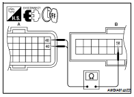
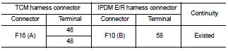
4. Disconnect fuse block J/B harness connector E6.
5. Check continuity between TCM harness connector F16 terminal 45, 47 and fuse block J/B harness connector E6 terminal 12P.
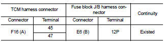
Is the inspection result normal? YES >> GO TO 5.
NO >> Repair or replace damaged parts.
5.CHECK HARNESS BETWEEN TCM AND IPDM E/R AND BETWEEN TCM AND BATTERY (PART 2)
Check continuity between TCM harness connector F16 terminal 45, 46, 47, 48 and ground.
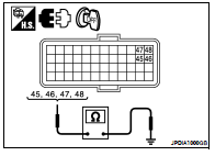
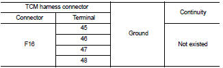
Is the inspection result normal? YES >> Check the following. If NG, repair or replace damaged parts.
• 10A fuse (No. 34, located in IPDM E/R) • 10A fuse (No. 11, located in fuse block) • Ignition switch.Refer to PG-74, "Wiring Diagram — Battery Power Supply —".
NO >> Repair or replace damaged parts.
6.DETECT MALFUNCTIONING ITEMS
Check TCM connector pin terminals for damage or loose connection with harness connector.
Is the inspection result normal? YES >> Replace TCM. Refer to TM-254, "Exploded View".
NO >> Repair or replace damaged parts.
 P0868 secondary pressure down
 P1705 throttle position sensor