Nissan Altima (L32) 2007-2012 Service Manual: P1777 step motor
Description
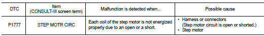
The step motor changes the step with turning 4 coils ON/OFF according to the signal from TCM. As a result, the flow of line pressure to primary pulley is changed and pulley ratio is controlled
DTC Logic
DTC DETECTION LOGIC
DTC CONFIRMATION PROCEDURE
CAUTION: Always drive vehicle at a safe speed. NOTE: If “DTC CONFIRMATION PROCEDURE” has been previously performed, always turn ignition switch OFF.
Then wait at least 10 seconds before performing the next test.
1.CHECK DTC DETECTION

1. Start engine.
2. Drive vehicle for at least 5 consecutive seconds.
3. Perform “SELF-DIAG RESULTS” mode for “TRANSMISSION”.

Follow the procedure “With CONSULT-III”.
Is “P1777 STEP MOTR CIRC” detected? YES >> Go to TM-361, "Diagnosis Procedure".
NO >> Check intermittent incident. Refer to GI-42, "Intermittent Incident".
Diagnosis Procedure
1.CHECK STEP MOTOR CIRCUIT
1. Turn ignition switch OFF.
2. Disconnect TCM harness connector.
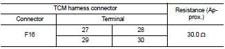
3. Check resistance between TCM harness connector F16 terminal 27, 29 and 28, 30.
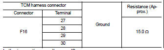
4. Check resistance between TCM harness connector F16 terminal 27, 28, 29, 30 and ground.
Is the inspection result normal? YES >> GO TO 5.
NO >> GO TO 2.
2.CHECK HARNESS BETWEEN TCM AND CVT UNIT (STEP MOTOR) (PART 1)
1. Disconnect CVT unit harness connector.
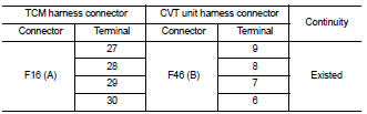
2. Check continuity between TCM harness connector F16 (A) terminal 27, 28, 29, 30 and CVT unit harness connector F46 (B) terminal 9, 8, 7, 6.
Is the inspection result normal? YES >> GO TO 3.
NO >> Repair or replace damaged parts.
3.CHECK HARNESS BETWEEN TCM AND CVT UNIT (STEP MOTOR) (PART 2)
Check continuity between TCM harness connector F16 terminal 27, 28, 29, 30 and ground.
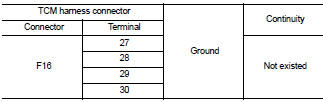
Is the inspection result normal? YES >> GO TO 4.
NO >> Repair or replace damaged parts.
4.CHECK STEP MOTOR
Check step motor. Refer to TM-363, "Component Inspection (Step Motor)".
Is the inspection result normal? YES >> GO TO 6.
NO >> GO TO 5.
5.CHECK DTC

1. Turn ignition switch ON.
2. Perform “SELFDIAG RESULTS” mode for “TRANSMISSION”.
Is “P1777 STEP MOTER CIRC” detected? YES (Only DTC P1777 detected)>>Replace control valve. Refer to TM-447, "Exploded View".
YES (DTC P0725 and DTC U1000 in addition to DTC P1777 are detected)>>When DTC is detected as listed below, replace control valve. Refer to TM-447, "Exploded View".
• DTC for P1777 and P0725 are detected.
• DTC for P1777 and U1000 are detected.
• DTC for P1777, P0725 and U1000 are detected.
NO >> Replace transaxle assembly. Refer to TM-447, "Removal and Installation".
6.DETECT MALFUNCTIONING ITEMS
Check TCM connector pin terminals for damage or loose connection with harness connector.
Is the inspection result normal? YES >> Replace TCM. Refer to TM-430, "Exploded View".
NO >> Repair or replace damaged parts.
Component Inspection (Step Motor)
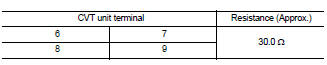
1.CHECK STEP MOTOR
1. Check resistance between CVT unit terminal 6, 8 and 7, 9.
2. Check resistance between CVT unit terminal 6, 7, 8, 9 and ground.
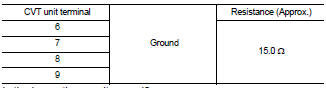
Is the inspection result normal? YES >> INSPECTION END
NO >> Perform “SELFDIAG RESULTS” mode for “TRANSMISSION”.
 P1745 line pressure control
 P1778 step motor - function