Nissan Altima (L32) 2007-2012 Service Manual: P1805 brake switch
Description
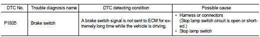
Brake switch signal is applied to the ECM through the stop lamp switch when the brake pedal is depressed.
This signal is used mainly to decrease the engine speed when the vehicle is driving.
DTC Logic
DTC DETECTION LOGIC
DTC CONFIRMATION PROCEDURE
1.PERFORM DTC CONFIRMATION PROCEDURE
1. Turn ignition switch ON.
2. Fully depress the brake pedal for at least 5 seconds.
3. Erase the DTC with CONSULT-III.
4. Check 1st trip DTC.
Is 1st trip DTC detected? YES >> Go to EC-406, "Diagnosis Procedure".
NO >> INSPECTION END
Diagnosis Procedure
1.CHECK STOP LAMP SWITCH CIRCUIT
1. Turn ignition switch OFF.
2. Check the stop lamp when depressing and releasing the brake pedal.
Is 1st trip DTC detected? YES >> GO TO 4.
NO >> GO TO 2.
2.CHECK STOP LAMP SWITCH POWER SUPPLY CIRCUIT
1. Turn ignition switch OFF.
2. Disconnect stop lamp switch harness connector.
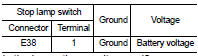
3. Check the voltage between stop lamp switch harness connector and ground.
Is the inspection result normal? YES >> GO TO 4.
NO >> GO TO 3.
3.DETECT MALFUNCTIONING PART
Check the following.
• Junction block connector E6
• 10A fuse (No. 7)
• Harness for open or short between stop lamp switch and battery
>> Repair open circuit or short to ground or short to power in harness or connectors.
4.CHECK STOP LAMP SWITCH INPUT SIGNAL CIRCUIT FOR OPEN AND SHORT
1. Disconnect ECM harness connector.
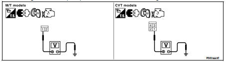
2. Check the continuity between ECM harness connector and stop lamp switch harness connector.
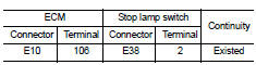
3. Also check harness for short to ground and short to power.
Is the inspection result normal? YES >> GO TO 6.
NO >> GO TO 5.
5.DETECT MALFUNCTIONING PART
Check the following.
• Junction block connector E44, E45
• Harness for open or short between ECM and stop lamp switch
>> Repair open circuit or short to ground or short to power in harness or connectors.
6.CHECK STOP LAMP SWITCH
Refer to EC-407, "Component Inspection (Stop Lamp Switch)".
Is the inspection result normal? YES >> GO TO 7.
NO >> Replace stop lamp switch.
7.CHECK INTERMITTENT INCIDENT
Refer to GI-42, "Intermittent Incident".
>> INSPECTION END
Component Inspection (Stop Lamp Switch)
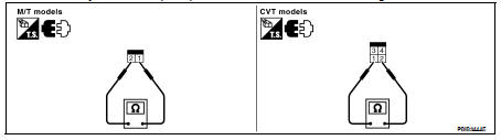
1.CHECK STOP LAMP SWITCH-I
1. Turn ignition switch OFF.
2. Disconnect stop lamp switch harness connector.
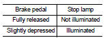
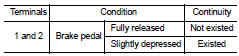
3. Check the continuity between stop lamp switch terminals under the following conditions.
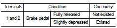
Is the inspection result normal? YES >> INSPECTION END
NO >> GO TO 2.
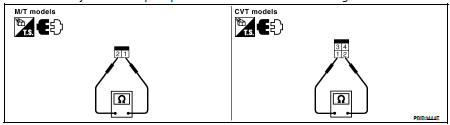
2.CHECK STOP LAMP SWITCH-II
1. Adjust stop lamp switch installation. Refer to BR-13, "Inspection and Adjustment".
2. Check the continuity between stop lamp switch terminals under the following conditions.
Is the inspection result normal? YES >> INSPECTION END
NO >> Replace stop lamp switch.
 P1715 input speed sensor (primary
speed sensor)
P1715 input speed sensor (primary
speed sensor) P2004 tumble control valve