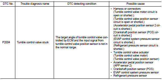
Nissan Altima (L32) 2007-2012 Service Manual: P2004 tumble control valve
Description
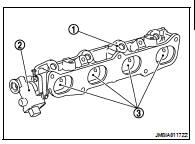
Tumble control valve (3) is installed in the intake manifold adapter (1).
Tumble control valve actuator (2) is connected to the front end of the valve shaft.
Tumble control valve actuator consists of motor and position sensor, etc.
The motor opens or closes the valve by the output signal of the ECM.
The sensor consists of a permanent magnet and Hall IC. It senses the valve shaft movement and feeds the voltage signals to the ECM.
DTC Logic
DTC DETECTION LOGIC
DTC CONFIRMATION PROCEDURE
1.PRECONDITIONING
If DTC Confirmation Procedure has been previously conducted, always turn ignition switch OFF and wait at least 10 seconds before conducting the next test.
TESTING CONDITION: • Before performing the following procedure, confirm that battery voltage is more than 11V at idle.
• Always perform the test at a temperature above 0°C (32°F) >> GO TO 2.
2.PERFORM DTC CONFIRMATION PROCEDURE

1. Turn ignition switch ON.
2. Select “DATA MONITOR” mode with CONSULT-III.
3. Make sure that “COOLAN TEMP/S” indicates between 5°C (41°F) to 60°C (140°F).
If not, cool engine down or warm engine up until “COOLAN TEMP/S” indicates between 5°C (41°F) to 60°C (140°F). Then go to the following steps.
4. Fully release accelerator pedal and wait at least 5 seconds.
5. Depress accelerator pedal and wait at least 5 seconds.
6. Check 1st trip DTC.

Following the procedure “With CONSULT-III” above.
Is 1st trip DTC detected? YES >> Go to EC-410, "Diagnosis Procedure".
NO >> INSPECTION END
Diagnosis Procedure
1.CHECK GROUND CONNECTION
1. Turn ignition switch OFF.
2. Check ground connection E9. Refer to Ground Inspection in GI-45, "Circuit Inspection".
Is the inspection result normal? YES >> GO TO 2.
NO >> Repair or replace ground connection.
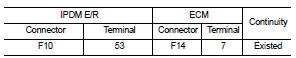
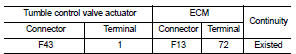
2.CHECK TUMBLE CONTROL VALVE MOTOR POWER SUPPLY CIRCUIT-I
Check the voltage between ECM harness connector and ground.
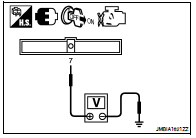
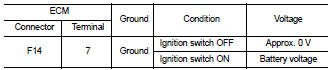
Is the inspection result normal? YES >> GO TO 4.
NO >> GO TO 3.
3.CHECK TUMBLE CONTROL VALVE MOTOR POWER SUPPLY CIRCUIT-II
1. Turn ignition switch OFF.
2. Disconnect ECM harness connector.
3. Disconnect IPDM E/R harness connector.
4. Check the continuity between IPDM E/R harness connector and ECM harness connector.
5. Also check harness for short to ground and short to power.
Is the inspection result normal? YES >> Refer to EC-144, "Diagnosis Procedure".
NO >> Repair open circuit or short to ground or short to power in harness or connectors.
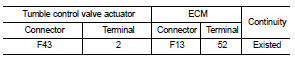
4.CHECK TUMBLE CONTROL VALVE MOTOR OUTPUT SIGNAL CIRCUIT FOR OPEN AND SHORT
1. Disconnect tumble control valve actuator harness connector.
2. Disconnect ECM harness connector.
3. Check the continuity between tumble control valve actuator harness connector and ECM harness connector.
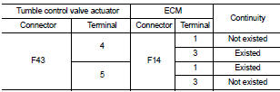
4. Also check harness for short to ground and short to power.
Is the inspection result normal? YES >> GO TO 5.
NO >> Repair open circuit or short to ground or short to power in harness or connectors.
5.CHECK TUMBLE CONTROL VALVE POSITION SENSOR POWER SUPPLY CIRCUIT-I
1. Reconnect ECM harness connector disconnected.
2. Turn ignition switch ON.
3. Check the voltage between tumble control valve actuator harness connector and ground.
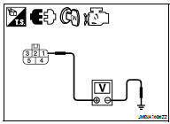
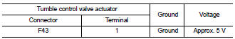
Is the inspection result normal? YES >> GO TO 11.
NO >> GO TO 6.
6.CHECK TUMBLE CONTROL VALVE POSITION SENSOR POWER SUPPLY CIRCUIT-II
1. Turn ignition switch OFF.
2. Disconnect ECM harness connector.
3. Check the continuity between tumble control valve actuator harness connector and ECM harness connector.
Is the inspection result normal? YES >> GO TO 7.
NO >> Repair open circuit.
7.CHECK TUMBLE CONTROL VALVE POSITION SENSOR POWER SUPPLY CIRCUIT-III
Check harness for short to power and short to ground, between the following terminals.
Is the inspection result normal? YES >> GO TO 8.
NO >> Repair short to ground or short to power in harness or connectors.
8.CHECK COMPONENTS
Check the following.
• Refrigerant pressure sensor (Refer to EC-482, "Diagnosis Procedure".) • Crankshaft position sensor (POS) (Refer to EC-281, "Component Inspection".) • EVAP control system pressure sensor (Refer to EC-318, "Component Inspection".) Is the inspection result normal? YES >> GO TO 9.
NO >> Replace malfunctioning components.
9.CHECK APP SENSOR
Refer to EC-429, "Component Inspection".
Is the inspection result normal? YES >> GO TO 14.
NO >> GO TO 10.
10.REPLACE ACCELERATOR PEDAL ASSEMBLY
1. Replace accelerator pedal assembly.
2. Refer to EC-429, "Special Repair Requirement".
>> INSPECTION END
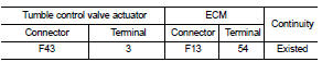
11.CHECK TUMBLE CONTROL VALVE POSITION SENSOR GROUND CIRCUIT FOR OPEN AND SHORT
1. Turn ignition switch OFF.
2. Disconnect ECM harness connector.
3. Check the continuity between tumble control valve actuator harness connector and ECM harness connector.
4. Also check harness for short to ground and short to power.
Is the inspection result normal? YES >> GO TO 12.
NO >> Repair open circuit or short to ground or short to power in harness or connectors.
12.CHECK TUMBLE CONTROL VALVE POSITION SENSOR INPUT SIGNAL CIRCUIT FOR OPEN AND SHORT
1. Check the continuity between tumble control valve actuator harness connector and ECM harness connector.
2. Also check harness for short to ground and short to power.
Is the inspection result normal? YES >> GO TO 13.
NO >> Repair open circuit or short to ground or short to power in harness or connectors.
13.CHECK TUMBLE CONTROL VALVE
Refer to EC-413, "Component Inspection".
Is the inspection result normal? YES >> GO TO 14.
NO >> Replace intake manifold adapter.
14.CHECK INTERMITTENT INCIDENT
Refer to GI-42, "Intermittent Incident".
Is the inspection result normal? YES >> Replace intake manifold adapter.
NO >> Repair or replace harness or connectors.
Component Inspection
1.CHECK TUMBLE CONTROL VALVE

1. Turn ignition switch OFF.
2. Remove intake manifold adapter. Refer to EM-26, "Removal and Installation".
3. Visually check the valve for damage and check if foreign matter is caught between the valve and the housing.
4. Connect tumble control valve actuator harness connector.
5. Turn ignition switch ON.
6. Perform “TUMBLE CONTROL VALVE” in “ACTIVE TEST” mode with CONSULT-III.
7. Touch “ON/OFF” and check that the valve opens and closes.

1. Turn ignition switch OFF.
2. Remove intake manifold adapter. Refer to EM-26, "Removal and Installation".
3. Visually check the valve for damage and check if foreign matter is caught between the valve and the housing.
4. Supply tumble control valve actuator terminals with battery voltage within 2 seconds and check operation.
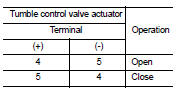
CAUTION: Do not apply 12V DC continuously for 30 seconds or more. Doing so may result in damage to the coil in tumble control valve motor.
Is the inspection result normal? YES >> INSPECTION END
NO >> Replace intake manifold adaptor.
 P1805 brake switch
 P2014 tumble control valve position
sensor
P2014 tumble control valve position
sensor