Nissan Altima (L32) 2007-2012 Service Manual: Parking brake control
PEDAL TYPE
Exploded View
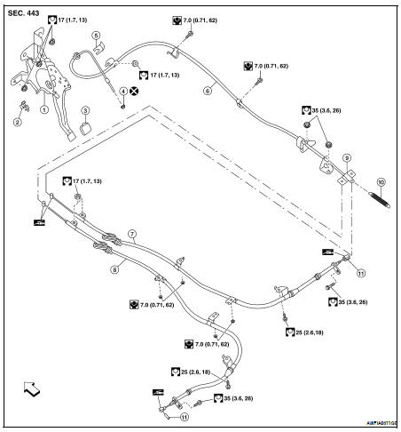
1. Control device assembly
2. Parking brake switch
3. Pedal pad
4. Adjusting nut
5. Lock plate
6. Front cable
7. Rear cable RH
8. Rear cable LH
9. Equalizer
10. Spring
11. Pin

Removal and Installation
REMOVAL
1. Remove rear wheel and tires. Refer to WT-66, "Adjustment".
2. Remove instrument lower cover and lower knee protector. Refer to IP-11, "Exploded View".
3. Disconnect parking brake switch connector.
4. Remove adjusting nut and discard, then loosen front cable.
CAUTION: Do not reuse adjusting nut. 5. Remove control device assembly nuts and remove control device assembly.
6. Remove center console. Refer to IP-11, "Exploded View".
7. Separate rear cables from front cable, remove front cable.
8. Remove heat insulator of the exhaust center tube.
9. Remove parking brake shoe, and remove rear cables from toggle lever. Refer to IP-11, "Exploded View".
10. Remove rear cable bolts and nuts, then remove rear cables.
INSTALLATION
Installation is in the reverse order of removal.
• Adjust the parking brake with new adjusting nut. Refer to PB-3, "PEDAL TYPE : Adjustment".
CAUTION: Do not reuse adjusting nut.
LEVER TYPE
Exploded View
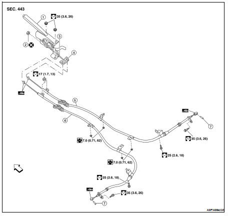
1. Control device assembly
2. Adjusting nut
3. Front cable
4. Equalizer
5. Rear cable (RH)
6. Rear cable (LH)
7. Pin

Removal and Installation
REMOVAL
1. Remove rear wheel and tires. Refer to WT-66, "Adjustment".
2. Remove center console. Refer to IP-18, "Disassembly and Assembly".
3. Disconnect parking brake switch connector.
4. Remove adjusting nut and discard. Loosen cable, then disconnect rear cables from equalizer.
CAUTION: Do not reuse adjusting nut. 5. Remove control device assembly nuts and remove control device assembly.
6. Remove heat insulator for the exhaust center tube.
7. Remove parking brake shoes, and disconnect rear cable from toggle lever. Refer to PB-9, "Removal and Installation".
8. Remove rear cable bolts and nuts, then remove rear cables.
INSTALLATION
Installation is in the reverse order of removal.
• Adjust parking brake. Refer to PB-4, "LEVER TYPE : Adjustment".
CAUTION: Do not reuse adjusting nut.
 On-vehicle repair
 Parking brake shoe