Nissan Altima (L32) 2007-2012 Service Manual: Parking brake shoe
Exploded View
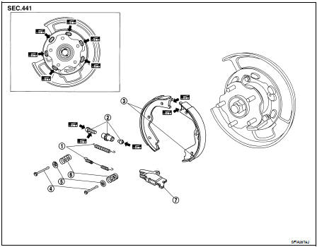
1. Return spring
2. Adjuster
3. Brake shoe
4. Anti-rattle pin
5. Retainer
6. Anti-rattle spring
7. Toggle lever
 PBC (Poly Butyl Cuprysil) grease
or silicone-based grease
PBC (Poly Butyl Cuprysil) grease
or silicone-based grease
Removal and Installation
WARNING: • Clean brakes with a vacuum dust collector to minimize the hazard of air borne particles or other materials.
• Clean dust on disc rotor and back plate using a vacuum dust collector. Do not blow with compressed air.
CAUTION: Put matching marks on both disc rotor and wheel hub when removing disc rotor.
REMOVAL
1. Remove rear wheel and tires. Refer to WT-66, "Adjustment".
2. Remove rear disc rotor with parking brake control device assembly in the fully released position. Refer to BR-35, "BRAKE CALIPER ASSEMBLY : Removal and Installation".
3. If disc rotor cannot be removed, remove as follows: a. Secure the disc rotor in place with wheel nuts and remove adjuster hole plug.
b. Rotate adjuster in direction (B) to retract and loosen brake shoe, using tool as shown.
4. Remove anti-rattle pins, retainers, anti-rattle springs, and return springs.
5. Remove parking brake shoes, adjuster assembly, and toggle lever.
6. Remove the back plate.
INSTALLATION
Installation is in the reverse order of removal. Note the following.
• Apply PBC (Poly Butyl Cuprysil) grease or equivalent to the specified points during assembly.
• Assemble adjusters so that threaded part is expanded when rotating it in the direction shown.
• Shorten adjuster by rotating it as shown.
• Check shoe sliding surface and drum inner surface for grease.
Wipe it off if it adhere on the surfaces.
• Perform break-in operation as follows after replacing brake shoes or disc rotors, or if brakes do not function well.
1. Adjust parking brake control device assembly stroke to the specified amount. Refer to PB-4, "LEVER TYPE : Adjustment".
2. Perform parking brake break-in (drag run) operation by driving vehicle under the following conditions: • Drive the vehicle forward.
• Maintain vehicle speed at approximately 40 km/h (25 MPH) keeping it constant in forward direction.
• Apply the parking brake at an operating force of approximately 400 N (40 kg, 88 lb) with constant force.
• Release the parking brake after approximately 10 seconds.
3. Check parking brake control device assembly stroke of parking brake. Readjust as necessary if it is outside the standard specifications.
 Parking brake control
 Service data and specifications
(SDS)
Service data and specifications
(SDS)