Nissan Altima (L32) 2007-2012 Service Manual: Parking brake switch signal circuit
Description
Transmits the parking brake switch signal to the combination meter.
Component Function Check
1.COMBINATION METER INPUT SIGNAL
1. Select “METER/M&A” on CONSULT-III.
2. Monitor “PKB SW” of “DATA MONITOR” while applying and releasing the parking brake.
>> Inspection End.
Diagnosis Procedure
COUPE
1.CHECK PARKING BRAKE SWITCH CIRCUIT
1. Disconnect combination meter connector and parking brake switch connector.
2. Check continuity between combination meter harness connector M24 (A) terminal 26 and parking brake switch harness connector M73 (B) terminal 1.

3. Check continuity between combination meter harness connector M24 (A) terminal 26 and ground.

Is the inspection result normal? YES >> Inspection End.
NO >> Repair harness or connector.
SEDAN
1.CHECK PARKING BRAKE SWITCH CIRCUIT
1. Disconnect combination meter connector and parking brake switch connector.
2. Check continuity between combination meter harness connector M24 (A) terminal 26 and parking brake switch harness connector M73 (B) (with M/T) or E35 (B) (with CVT) terminal 1.

3. Check continuity between combination meter harness connector M24 (A) terminal 26 and ground.

Is the inspection result normal? YES >> Inspection End.
NO >> Repair harness or connector.
Component Inspection
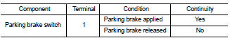
1.CHECK PARKING BRAKE SWITCH
Check continuity between parking brake switch terminal 1 and switch case ground.
Is the inspection result normal? YES >> Inspection End.
NO >> Replace parking brake switch.
 Oil pressure switch signal circuit
 Washer level switch signal circuit