Nissan Altima (L32) 2007-2012 Service Manual: Parking, license plate and tail lamps
System Diagram
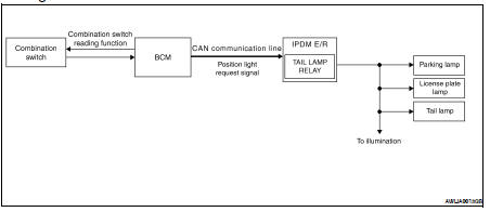
System Description
• BCM (Body Control Module) controls parking, license plate and tail lamps operation.
• IPDM E/R (Intelligent Power Distribution Module Engine Room) operates parking, license plate and tail lamps according to CAN communication signals from BCM.
Component Parts Location
1. IPDM E/R E17, E18, E201
2. BCM M16, M17, M18, M19 (view with instrument panel removed)
2. BCM M16, M17, M18, M19 (view with instrument panel removed)
Component Description
PARKING, LICENSE PLATE AND TAIL LAMPS OPERATION
When the lighting switch is in 1ST position, BCM detects the LIGHTING SWITCH 1ST POSITION ON. The BCM sends a parking light ON request through the CAN communication lines to the IPDM E/R. The IPDM E/R then activates the tail lamp relay which sends power to the parking and instrument illumination circuits.
EXTERIOR LAMP BATTERY SAVER CONTROL
With the lighting switch (combination switch) in the 2nd position and the ignition switch is turned from ON or ACC to OFF, the battery saver feature is activated.
Under this condition, the headlamps remain illuminated for 5 minutes unless the lighting switch position is changed. If the lighting switch position is changed, then the headlamps are turned off.
This setting can be changed by CONSULT-III. Refer to EXL-30, "BATTERY SAVER : CONSULT-III Function".
 Turn signal and hazard warning
lamps
Turn signal and hazard warning
lamps Combination switch reading system