Nissan Altima (L32) 2007-2012 Service Manual: Passenger side door mirror defogger
Description
Heats the heating wire with the power supply from the rear window defogger relay to prevent the door mirror from fogging up.
Component Function Check
1.CHECK DOOR MIRROR DEFOGGER RH
Check that the heating wire of door mirror defogger RH is heated when turning the rear window defogger switch ON.
Is the inspection result normal? YES >> Door mirror defogger RH is OK.
NO >> Refer to DEF-17, "Diagnosis Procedure".
Diagnosis Procedure
1. CHECK POWER SUPPLY CIRCUIT
1. Turn ignition switch OFF.
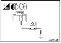
2. Disconnect door mirror RH.
3. Turn ignition switch ON.
4. Check voltage between door mirror RH connector and ground.

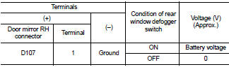
Is the inspection result normal? YES >> GO TO 2
NO >> Repair or replace harness.
2. CHECK GROUND CIRCUIT
1. Turn ignition switch OFF.
2. Check continuity between door mirror RH connector and ground.
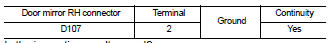
Is the inspection result normal? YES >> GO TO 3
NO >> Repair or replace harness.
3. CHECK PASSENGER SIDE DOOR MIRROR DEFOGGER
Check door mirror defogger RH.
Refer to DEF-18, "Component Inspection".
Is the inspection result normal? YES >> GO TO 4
NO >> Replace door mirror RH. Refer to MIR-19, "Removal and Installation".
4. CHECK INTERMITTENT INCIDENT
Check intermittent incident.
Refer to GI-42, "Intermittent Incident".
Is the inspection result normal? YES >> Check the following.
• Battery power supply circuit.
• Fuse block (J/B).
NO >> Repair or replace the malfunctioning parts.
Component Inspection
1. CHECK DOOR MIRROR DEFOGGER RH
1. Turn ignition switch OFF.
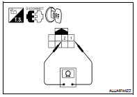
2. Disconnect door mirror RH.
3. Check continuity between door mirror terminals.
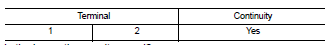
Is the inspection result normal? YES >> Inspection End.
NO >> Replace door mirror RH. Refer to MIR-19, "Removal and Installation".
 Driver side door mirror defogger
 ECU diagnosis