Nissan Altima (L32) 2007-2012 Service Manual: Positive crankcase ventilation
Description
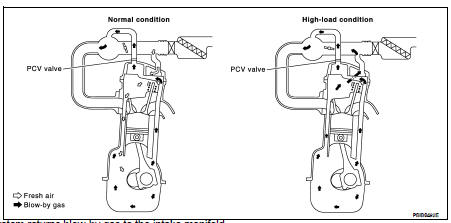
This system returns blow-by gas to the intake manifold.
The positive crankcase ventilation (PCV) valve is provided to conduct crankcase blow-by gas to the intake manifold.
During partial throttle operation of the engine, the intake manifold sucks the blow-by gas through the PCV valve.
Normally, the capacity of the valve is sufficient to handle any blow-by and a small amount of ventilating air.
The ventilating air is drawn from the air inlet tubes into the crankcase. In this process the air passes through the hose connecting air inlet tubes to rocker cover.
Under full-throttle condition, the manifold vacuum is insufficient to draw the blow-by flow through the valve.
The flow goes through the hose connection in the reverse direction.
On vehicles with an excessively high blow-by, the valve does not meet the requirement. This is because some of the flow will go through the hose connection to the air inlet tubes under all conditions.
Component Inspection
1.CHECK PCV VALVE
With engine running at idle, remove PCV valve from rocker cover. A properly working valve makes a hissing noise as air passes through it. A strong vacuum should be felt immediately when a finger is placed over valve inlet.
Is the inspection result normal? YES >> INSPECTION END
NO >> Replace PCV valve.
 On board refueling vapor recovery
(ORVR)
On board refueling vapor recovery
(ORVR) Refrigerant pressure sensor