Nissan Altima (L32) 2007-2012 Service Manual: Power supply and ground circuit
Diagnosis Procedure
1.CHECK GROUND CONNECTION
1. Turn ignition switch OFF.
2. Check ground connection E9. Refer to Ground Inspection in GI-45, "Circuit Inspection".
Is the inspection result normal? YES >> GO TO 2.
NO >> Repair or replace ground connection.
2.CHECK ECM GROUND CIRCUIT FOR OPEN AND SHORT
1. Disconnect ECM harness connector.
2. Check the continuity between ECM harness connector and ground.
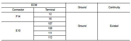
3. Also check harness for short to power.
is the inspection result normal? YES >> GO TO 4.
NO >> GO TO 3.
3.DETECT MALFUNCTIONING PART
Check the following.
• Harness connectors E11, F2
• Harness for open or short between ECM and ground
>> Repair open circuit or short to power in harness or connectors.
4.CHECK ECM POWER SUPPLY CIRCUIT-I
1. Reconnect ECM harness connector.
2. Turn ignition switch OFF and then ON.
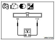
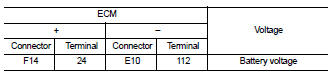
3. Check the voltage between ECM harness connectors.
Is the inspection result normal? YES >> GO TO 6.
NO >> GO TO 5.
5.DETECT MALFUNCTIONING PART
Check the following.
• IPDM E/R connector E18
• 10 A fuse (No. 35) • Harness for open or short between ECM and IPDM E/R
>> Repair open circuit, short to ground or short to power in harness or connectors.
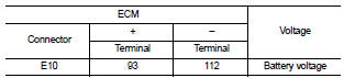
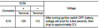
6.CHECK ECM POWER SUPPLY CIRCUIT-II
1. Turn ignition switch OFF and wait at least 10 seconds.
2. Check the voltage between ECM harness connectors.
Is the inspection result normal? YES >> GO TO 7.
NO >> GO TO 9.
7.CHECK ECM POWER SUPPLY CIRCUIT-III
1. Turn ignition switch ON.
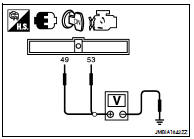
2. Check the voltage between IPDM E/R harness connector and ground.
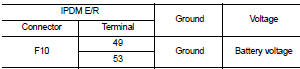
Is the inspection result normal? YES >> GO TO 8.
NO >> Replace IPDM E/R.
8.CHECK INTERMITTENT INCIDENT
Refer to GI-42, "Intermittent Incident".
>> INSPECTION END
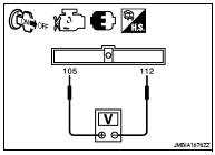
9.CHECK ECM POWER SUPPLY CIRCUIT-IV
1. Turn ignition switch OFF and wait at least 10 seconds.
2. Check the voltage between ECM harness connectors.
Is the inspection result normal? YES >> GO TO 12.
NO >> GO TO 10.
10.CHECK ECM POWER SUPPLY CIRCUIT-V
1. Disconnect ECM harness connector.
2. Disconnect IPDM E/R harness connector.
3. Check the continuity between ECM harness connector and IPDM E/R harness connector.
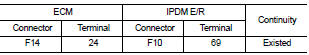
4. Also check harness for short to ground and short to power.
Is the inspection result normal? YES >> GO TO 11.
NO >> Repair open circuit, short to ground or short to power in harness or connectors.
11.CHECK 15 A FUSE
1. Disconnect 15 A fuse (No. 42) from IPDM E/R.
2. Check 15 A fuse.
Is the inspection result normal? YES >> GO TO 13.
NO >> Replace 15 A fuse.
12.CHECK ECM POWER SUPPLY CIRCUIT-VI
1. Disconnect ECM harness connector.
2. Disconnect IPDM E/R harness connector.
3. Check the continuity between ECM harness connector and IPDM E/R harness connector.
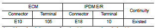
4. Also check harness for short to ground and short to power.
Is the inspection result normal? YES >> GO TO 13.
NO >> Repair open circuit, short to ground or short to power in harness or connectors.
13.CHECK INTERMITTENT INCIDENT
Refer to GI-42, "Intermittent Incident".
Is the inspection result normal? YES >> Replace IPDM E/R.
NO >> Repair or replace harness or connectors.
 Trouble diagnosis - specification
value
Trouble diagnosis - specification
value U0101 can comm circuit