Nissan Altima (L32) 2007-2012 Service Manual: Power window main switch
Description
• BCM supplies power.
• It operates each power window motor via corresponding power window switch and makes window move up/ down when main power window and door lock/unlock switch is operated.
Component Function Check
Main Power Window And Door Lock/unlock Switch
1. CHECK MAIN POWER WINDOW AND DOOR LOCK/UNLOCK SWITCH FUNCTION
Does power window motor operate with main power window and door lock/unlock switch operation? Is the inspection result normal? YES >> Main power window and door lock/unlock switch power supply and ground circuit are OK.
NO >> Refer to PWC-103, "POWER WINDOW MAIN SWITCH : Diagnosis Procedure".
Diagnosis Procedure
Main Power Window And Door Lock/unlock Switch Power Supply Circuit Check
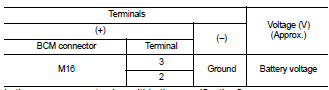
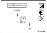
1. CHECK POWER SUPPLY CIRCUIT
1. Turn ignition switch ON.
2. Check voltage between main power window and door lock/ unlock switch connectors (A and B) and ground.
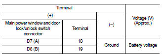
Is the measurement value within the specification? YES >> GO TO 3
NO >> GO TO 2
2. CHECK HARNESS CONTINUITY
1. Turn ignition switch OFF.
2. Disconnect BCM and main power window and door lock/unlock switch.
3. Check continuity between BCM connector (A) and main power window and door lock/unlock switch connectors (B and C).
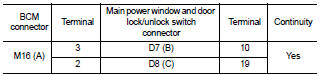
4. Check continuity between BCM connector and ground.
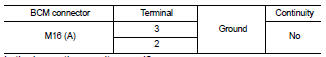
Is the inspection result normal? YES >> GO TO 4
NO >> Repair or replace harness.
3. CHECK GROUND CIRCUIT
1. Turn ignition switch OFF.
2. Disconnect main power window and door lock/unlock switch.
3. Check continuity between main power window and door lock/ unlock switch connector and ground.
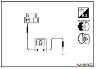
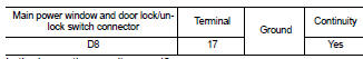
Is the inspection result normal? YES >> Replace main power window and door lock/unlock switch. Refer to PWC-186, "Removal and Installation".
After that, refer to PWC-108, "POWER WINDOW MAIN SWITCH : Special Repair Requirement".
NO >> Repair or replace harness.
4. CHECK BCM OUTPUT SIGNAL
1. Connect BCM.
2. Turn ignition switch ON.
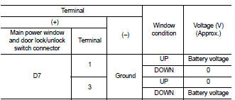
3. Check voltage between BCM connector and ground.
Is the measurement value within the specification? YES >> Check main power window and door lock/unlock switch output signal (rear power window switch LH) GO TO 5
YES >> Check main power window and door lock/unlock switch output signal (rear power window switch RH) GO TO 6
NO >> Replace BCM. Refer to BCS-96, "Removal and Installation".
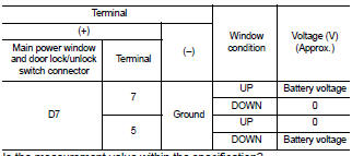
5. CHECK MAIN POWER WINDOW AND DOOR LOCK/UNLOCK SWITCH OUTPUT SIGNAL (REAR POWER WINDOW SWITCH LH)
1. Connect main power window and door lock/unlock switch.
2. Turn ignition switch ON.
3. Check voltage between main power window and door lock/ unlock switch and ground.
Is the measurement value within the specification? YES >> GO TO 7
NO >> Replace main power window and door lock/unlock switch. Refer to PWC-186, "Removal and Installation". After that, refer to PWC-108, "POWER WINDOW MAIN SWITCH : Special Repair Requirement".
6. CHECK MAIN POWER WINDOW AND DOOR LOCK/UNLOCK SWITCH OUTPUT SIGNAL (REAR POWER WINDOW SWITCH RH)
1. Connect main power window and door lock/unlock switch.
2. Turn ignition switch ON.
3. Check voltage between main power window and door lock/ unlock switch and ground.
Is the measurement value within the specification? YES >> GO TO 8
NO >> Replace main power window and door lock/unlock switch. Refer to PWC-186, "Removal and Installation". After that, refer to PWC-108, "POWER WINDOW MAIN SWITCH : Special Repair Requirement".
7. CHECK HARNESS CONTINUITY (REAR POWER WINDOW SWITCH LH)
1. Turn ignition switch OFF.
2. Disconnect main power window and door lock/unlock switch and rear power window switch LH.
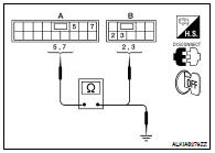
3. Check continuity between main power window and door lock/ unlock switch connector (A) and rear power window switch LH connector (B).
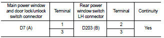
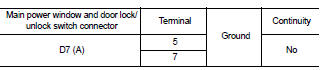
4. Check continuity between main power window and door lock/unlock switch connector (A) and ground.

Is the inspection result normal? YES >> GO TO 9
NO >> Repair or replace harness.
8. CHECK HARNESS CONTINUITY (REAR POWER WINDOW SWITCH RH)
1. Turn ignition switch OFF.
2. Disconnect main power window and door lock/unlock switch and rear power window switch RH.
3. Check continuity between main power window and door lock/ unlock switch connector (A) and rear power window switch RH connector (B).
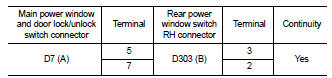
4. Check continuity between main power window and door lock/unlock switch connector and ground.
Is the inspection result normal? YES >> GO TO 9
NO >> Repair or replace harness.
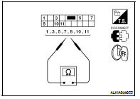
9. CHECK MAIN POWER WINDOW AND DOOR LOCK/UNLOCK SWITCH
Check main power window and door lock/unlock switch.
Refer to PWC-106, "POWER WINDOW MAIN SWITCH : Component Inspection".
Is the inspection result normal? YES >> Check intermittent incident. Refer to GI-42, "Intermittent Incident".
NO >> Replace main power window and door lock/unlock switch. Refer to PWC-186, "Removal and Installation". After that, refer to PWC-108, "POWER WINDOW MAIN SWITCH : Special Repair Requirement".
Component Inspection
1. CHECK MAIN POWER WINDOW AND DOOR LOCK/UNLOCK SWITCH
1. Check main power window and door lock/unlock switch.
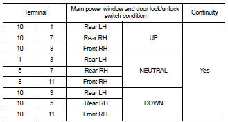
2. Check continuity between main power window and door lock/ unlock switch (power window lock switch) (Lock operation).
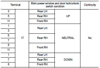
3. Check continuity between main power window and door lock/ unlock switch (power window lock switch) (Unlock operation).
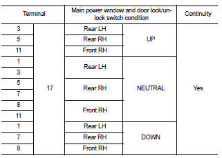
Is the inspection result normal? YES >> Main power window and door lock/unlock switch is OK.
NO >> Replace main power window and door lock/unlock switch. Refer to PWC-186, "Removal and Installation". After that, refer to PWC-108, "POWER WINDOW MAIN SWITCH : Special Repair Requirement".
Special Repair Requirement
1. PERFORM INITIALIZATION PROCEDURE
Perform initialization procedure.
Refer to PWC-95, "ADDITIONAL SERVICE WHEN REPLACING CONTROL UNIT : Special Repair Requirement".
Is the inspection result normal? YES >> GO TO 2
NO >> Check intermittent incident. Refer to GI-42, "Intermittent Incident".
2. CHECK ANTI-PINCH OPERATION
Check anti-pinch operation.
Refer to PWC-95, "ADDITIONAL SERVICE WHEN REPLACING CONTROL UNIT : Special Repair Requirement".
Is the inspection result normal? YES >> Inspection end.
NO >> Refer to PWC-103, "POWER WINDOW MAIN SWITCH : Component Function Check".
 Power supply and ground circuit
 Front power window switch