Nissan Altima (L32) 2007-2012 Service Manual: Rear combination lamp
Bulb Replacement
Removal
1. Remove the rear combination lamp. Refer to EXL-260, "Removal and Installation".
2. Turn the rear turn signal lamp bulb socket counterclockwise and remove it.
3. Remove the rear turn signal lamp bulb.
Installation
Installation is in the reverse order of removal.
STOP/TAIL LAMP
Removal
1. Remove the rear combination lamp. Refer to EXL-260, "Removal and Installation".
2. Turn the stop/tail lamp bulb socket counterclockwise and remove it.
3. Remove the stop/tail lamp bulb.
Installation
Installation is in the reverse order of removal.
BACK-UP LAMP
Removal
1. Remove the rear combination lamp. Refer to EXL-260, "Removal and Installation".
2. Turn the back-up lamp bulb socket counterclockwise and remove it.
3. Remove the back-up lamp bulb.
Installation
Installation is in the reverse order of removal.
SIDE MARKER LAMP
Removal
1. Remove the rear combination lamp. Refer to EXL-260, "Removal and Installation".
2. Turn the side marker lamp bulb socket counterclockwise and remove it.
3. Remove the side marker lamp bulb.
Installation
Installation is in the reverse order of removal.
Removal and Installation
COMPONENTS
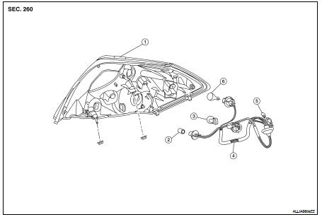
1. Rear combination lamp assembly
2. Back-up lamp bulb
3. Stop/Tail lamp bulb
4. Rear combination lamp harness
5. Side marker lamp bulb
6. Rear turn signal lamp bulb
REMOVAL
1. Remove trunk side finisher. Refer to INT-23, "Removal and Installation".
2. Remove the rear combination lamp nuts.
3. Pull the rear combination lamp assembly toward rear of the vehicle and remove.
INSTALLATION
Installation is the reverse order of removal.
 License plate lamp
 Lighting and turn signal switch