Nissan Altima (L32) 2007-2012 Service Manual: Rear lower link & coil spring
Removal and Installation
Removal
1. Loosen the rear lower link bolt and nut from the suspension member side.
2. Support the rear lower link by placing a suitable jack under the knuckle.
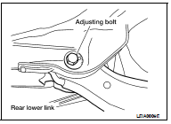
3. Remove the rear lower link adjusting bolt and nut from the suspension member side using power tool.
• Do not reuse the adjusting nut, use a new adjusting nut for installation.
4. Slowly lower the jack to lower the rear lower link and coil spring.
5. Remove the upper rubber seat, coil spring, and lower rubber seat from the rear lower link.
6. Remove rear lower link bolt and nut from the suspension member side using power tool.
7. Remove the rear lower link.

Installation
Installation is in the reverse order of removal.
• Do not reuse the adjusting nut, use a new adjusting nut for installation.
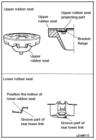
• Check that the projecting part inside the upper rubber seat and the bracket flange are attached as shown.
• Check that the projection part outside the upper rubber seat is directed toward the front of the vehicle.
• Position the hollow of the lower rubber seat with the groove part of the rear lower link.
• Install the coil spring so that the side with the two paint markers is directed toward the lower side.
• Check the rear wheel alignment and adjust if necessary. Refer to RSU-18, "Rear Wheel Alignment (Unladen*)".


 On-vehicle repair
 Front lower link