Nissan Altima (L32) 2007-2012 Service Manual: Rear power window switch
Description
• BCM supplies power.
• Rear power window motor will be operated if rear power window switch is operated. Rear power window switch.
Component Function Check
Rear Power Window Switch
1. CHECK REAR POWER WINDOW MOTOR FUNCTION
Does rear power window motor operate with rear power window switch operation? Is the inspection result normal?
YES >> Rear power window switch power supply and ground circuit are OK.
NO >> Refer to PWC-111, "REAR POWER WINDOW SWITCH : Diagnosis Procedure".
Diagnosis Procedur
Rear Power Window Switch Power Supply Circuit Check
1. CHECK POWER SUPPLY CIRCUIT
1. Turn ignition switch ON.
2. Check voltage between rear power window switch connector and ground.
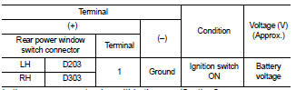
Is the measurement value within the specification? YES >> GO TO 2 (Rear power window switch LH) YES >> GO TO 3 (Rear power window switch RH) NO >> GO TO 4
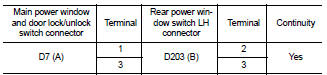
2. CHECK HARNESS CONTINUITY (REAR POWER WINDOW SWITCH LH)
1. Turn ignition switch OFF.
2. Disconnect main power window and door lock/unlock switch and rear power window switch LH.
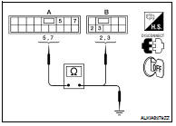
3. Check continuity between main power window and door lock/ unlock switch connector (A) and rear power window switch LH connector (B).
4. Check continuity between main power window and door lock/unlock switchh connector (A) and ground.
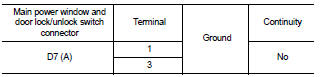
Is the inspection result normal? YES >> Check intermittent incident. Refer to GI-42, "Intermittent Incident".
NO >> Repair or replace harness.
3. CHECK HARNESS CONTINUITY (REAR POWER WINDOW SWITCH RH)
1. Turn ignition switch OFF.
2. Disconnect main power window and door lock/unlock switch and rear power window switch RH.
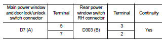
3. Check continuity between main power window and door lock/ unlock switch connector (A) and rear power window switch RH connector (B).
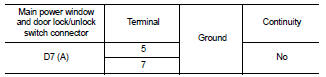
4. Check continuity between main power window and door lock/unlock switch connector (A) and ground.
Is the inspection result normal? YES >> Check intermittent incident. Refer to GI-42, "Intermittent Incident".
NO >> Repair or replace harness.
Is the inspection result normal? YES >> Check intermittent incident. Refer to GI-42, "Intermittent Incident".
NO >> Repair or replace harness.
4. CHECK HARNESS CONTINUITY
1. Disconnect BCM and rear power window switch.
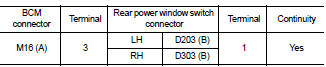
2. Check continuity between BCM connector (A) and rear power window switch connector (B).
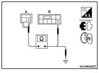
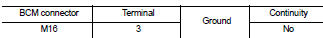
3. Check continuity between BCM connector and ground.
Is the inspection result normal? YES >> GO TO 5
NO >> Repair or replace harness.
5. CHECK REAR POWER WINDOW SWITCH
Check rear power window switch.
Refer to PWC-112, "REAR POWER WINDOW SWITCH : Component Inspection".
Is the inspection result normal? YES >> Check intermittent incident. Refer to GI-42, "Intermittent Incident".
NO >> Replace rear power window switch. Refer to PWC-186, "Removal and Installation".
Component Inspection
1. CHECK REAR POWER WINDOW SWITCH
Check rear power window switch.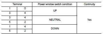
Is the inspection result normal? YES >> Rear power window switch is OK.
NO >> Replace rear power window switch. Refer to PWC-186, "Removal and Installation".
 Front power window switch
 Power window motor