Nissan Altima (L32) 2007-2012 Service Manual: Road wheel tire assembly
Adjustment
WHEEL BALANCE
1. Remove inner and outer balance weights from the wheel.
CAUTION: • Be careful not to scratch the wheel during removal procedures. 2. Using releasing agent, remove double-faced adhesive tape from the wheel.
CAUTION: • Be careful not to scratch the wheel during removal.
• After removing double-faced adhesive tape, wipe clean traces of releasing agent from the wheel. 3. Set wheel on wheel balancer using the center hole as a guide. Start the tire balance machine.
• If a tire balance machine has adhesion balance weight mode settings and drive-in weight mode setting, select and adjust a drive-in weight mode suitable for wheels.
4. When inner and outer unbalance values are shown on the wheel balancer indicator, multiply outer unbalance value by 1.6 to determine balance weight that should be used. Select the outer balance weight with a value closest to the calculated value and install it to the designated outer position of, or at the designated angle in relation to the road wheel.
CAUTION: • Do not install the inner balance weight before installing the outer balance weight.
• Before installing the balance weight, be sure to clean the mating surface of the wheel.
 Indicated unbalance value × 5/3 = balance weight to be installed
Calculation example:
23 g (0.81 oz.) × 5/3 = 38.33 g (1.35 oz.) = 40 g (1.41 oz.) balance weight
(closer to calculated balance
weight value)
Note that balance weight value must be closer to the calculated balance weight
value.
Indicated unbalance value × 5/3 = balance weight to be installed
Calculation example:
23 g (0.81 oz.) × 5/3 = 38.33 g (1.35 oz.) = 40 g (1.41 oz.) balance weight
(closer to calculated balance
weight value)
Note that balance weight value must be closer to the calculated balance weight
value.
Example: 37.4 g = 35 g (1.23 oz.) 37.5 g = 40 g (1.41 oz.) a. Install balance weight in the position shown.
b. When installing balance weight to wheels, set it into the grooved area on the inner wall of the wheel as shown so that the balance weight center is aligned with the wheel balancer indication position (angle).
CAUTION: • Always use genuine Nissan adhesion balance weights.
• Balance weights are not reusable; always replace with new ones.
• Do not install more than three sheets of balance weight.
c. If calculated balance weight value exceeds 50 g (1.76 oz.), install two balance weight sheets in line with each other as shown.
CAUTION: Do not install one balance weight sheet on top of another.
5. Start wheel balancer again.
6. Install drive-in balance weight on inner side of road wheel in the wheel balancer indication position (angle).
CAUTION: Do not install more than two balance weights.
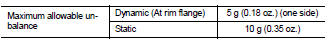
7. Start wheel balancer. Make sure that inner and outer residual unbalance values are 5 g (0.18 oz.) each or below.
• If either residual unbalance value exceeds 5 g (0.18 oz.), repeat installation procedures.
Wheel balance (Maximum allowable unbalance):
TIRE ROTATION
• Follow the maintenance schedule for tire rotation service intervals. Refer to MA-4, "Explanation General Maintenance".
• Do not include the T-type spare tire when rotating the tires.
CAUTION: • When installing wheels, tighten them diagonally by dividing the work two to three times in order to prevent the wheels from developing any distortion.
• Be careful not to tighten wheel nut at torque exceeding the criteria for preventing strain of disc rotor.
 Tire pressure receiver
 Removal and installation