Nissan Altima (L32) 2007-2012 Service Manual: Rocker cover
Removal and Installation
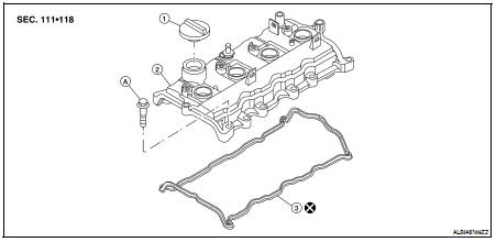
1. Oil filler cap
2. Rocker cover
3. Rocker cover gasket
A. Follow installation for tightening steps
REMOVAL
1. Disconnect the battery negative terminal. Refer to PG-68, "Removal and Installation" (Coupe models) or PG-139, "Removal and Installation" (Sedan models).
2. Remove the engine cover.
3. Remove the front air duct. Refer to EM-25, "Removal and Installation".
4. Remove the blow-by hose.
5. Remove the two brake ECU nuts and set the brake ECU aside. Refer to BRC-66, "Removal and Installation" (ABS), BRC-137, "Removal and Installation" (TCS/ABS) or BRC-239, "Removal and Installation" (VDC/TCS/ABS).
6. Remove the RH engine mount torque rod. Refer to EM-72, "Removal and Installation".
7. Use a suitable tool to support the engine assembly.
8. Remove the RH engine support bracket. Refer to EM-72, "Removal and Installation".
9. Remove the RH engine mounting bracket. Refer to EM-72, "Removal and Installation".
10. Disconnect the PCV hose.
11. Remove the ignition coils. Refer to EM-35, "Removal and Installation".
12. Disconnect the fuel injectors and position the fuel injector harness aside.
13. Loosen the bolts in the numerical order as shown using power tool.
14. Remove the rocker cover and the rocker cover gasket. Discard the rocker cover gasket.
CAUTION: Do not reuse the rocker cover gasket.
15. Remove the oil filler cap if necessary, to transfer to the new rocker cover.
INSTALLATION
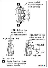
1. Apply RTV Silicone Sealant to the joint part of the cylinder head and camshaft bracket using the following steps: • Use Genuine Silicone RTV Sealant, or equivalent. Refer to GI-15.
a. Follow illustration (a) to apply sealant to joint part of No.1 camshaft bracket and cylinder head.
b. Follow illustration (b) to apply sealant in a 90° degree angle to the illustration (a).
2. Install the rocker cover and the new rocker cover gasket.
• The rocker cover gasket must be securely installed in the groove in the rocker cover.
3. Tighten the rocker cover bolts in two steps, in the numerical order as shown.
Step 1 : 1.96 N·m (0.20 kg-m, 17 in-lb)
Step 2 : 8.33 N·m (0.85 kg-m, 74 in-lb)
4. Installation of the remaining components is in the reverse order of removal.
 Fuel injector and fuel tube
 Camshaft