Nissan Altima (L32) 2007-2012 Service Manual: Shift fork and fork rod
Exploded View
Refer to TM-28, "Exploded View".
Disassembly
1. Remove return spring to striking rod assembly.
Assembly
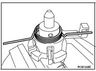
1. Temporarily install return spring to striking rod assembly.
CAUTION:
Be careful with the orientation of return spring.
2. Attach one end of the return spring to striking interlock of striking
rod assembly while holding return spring.
CAUTION:
• When installing, check that return spring is securely
seated in the groove of striking interlock of striking rod
assembly.
Inspection
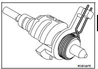
STRIKING ROD ASSEMBLY AND RETURN SPRING
• Check contact surfaces and sliding area for wear, damage, bending,
etc. If necessary, replace parts.
FORK ROD AND SHIFT FORK
• Check contact surfaces and sliding area for wear, damage, bending,
etc. If necessary, replace parts.
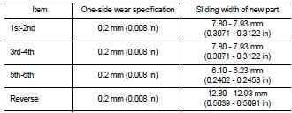
SHIFT FORK
• Check if the width of shift fork hook (sliding area with coupling
sleeve) is within allowable specification below.
Exploded View
Refer to TM-28, "Exploded View".
Disassembly
1. Remove final gear mounting bolts and then separate the final gear from
differential case.
2. Remove differential side ...
General Specifications
TRANSAXLE
FINAL GEAR
End Play
Baulk Ring Clearance
Dimension
Differential Side Bearing Preload
Differential Side Gear Clearance
...
Other materials: Rear-facing child restraint installation
using the seat belts
WARNING
The three-point seat belt with Automatic
Locking Retractor (ALR) must be
used when installing a child restraint.
Failure to use the ALR mode will result
in the child restraint not being properly
secured. The restraint could tip over or
be loose and cause injury to a child in a
sudden stop o ...
Supplemental air bag warning labels
Warning labels about the supplemental
front-impact air bag system are placed in
the vehicle as shown in the illustration.
WARNING
Do not use a rear-facing child restraint
on a seat protected by an air bag in
front of it. If the air bag deploys, it may
cause serious injury or death.
Supplemental air ...
Fuel gauge
The gauge indicates the approximate fuel
level in the tank.
The gauge may move slightly during braking,
turning, acceleration, or going up or
down hills.
The gauge needle returns to 0 (Empty) after
the ignition switch is placed in the OFF
position.
The low fuel warning message shows in
the vehic ...
 Final drive
 Service data and specifications
(SDS)
Service data and specifications
(SDS)