Nissan Altima (L32) 2007-2012 Service Manual: Final drive
Exploded View
Refer to TM-28, "Exploded View".
Disassembly
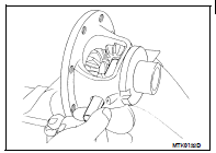
1. Remove final gear mounting bolts and then separate the final gear from differential case.
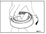
2. Remove differential side bearing (clutch housing side) using Tool and pullers (B).
Tool number : ST33061000 (J-8107-2)
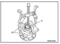
CAUTION: Hook a puller on the cage of differential side bearing.
3. Remove speedometer drive gear.
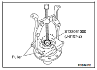
4. Remove differential side bearing (transaxle case side) using Tool and pullers.
Tool number : ST33061000 (J-8107-2)
CAUTION: Hook a puller on the inner race of differential side bearing.
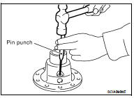
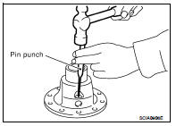
5. Remove retaining pin from differential case using suitable tool and then remove pinion mate shaft.
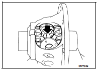
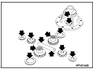
6. Rotate pinion mate gears and remove pinion mate gears, pinion mate thrust washers, side gears, and side gear thrust washers from differential case.
Assembly
1. Apply gear oil to sliding area of differential case, each gear, and thrust washer.
2. Install side gear thrust washers and side gears into differential case.
3. While rotating pinion mate thrust washers and pinion mate gears, aligning them diagonally, install them into differential case.
4. Insert pinion mate shaft into differential case.
CAUTION: Do not damage pinion mate thrust washers.
5. Measure end play of side gears following the procedure below.
Then select side gear thrust washer.
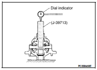
a. Put differential case vertically so that its side gear to be measured faces upward.
b. Place the Tool and a dial indicator onto side gears.
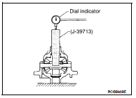
Tool number : — (J-39713)
c. Move side gears up and down to measure the clearance and select thrust washer so that it satisfies the standard value.
Allowable Clearance between side gear and differential case with thrust washer : Refer to TM-84, "Differential Side Gear Clearance".
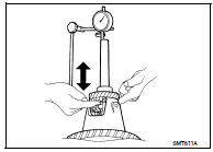
CAUTION: • There should be no resistance and gears should rotate freely.
• Place differential case upside down. Measure the end play for opposite side-gears likewise securely.
• Only one thrust washer can be selected.
6. Install retaining pin into pinion mate shaft using suitable tool.
CAUTION: Do not reuse retaining pin.
7. Press in differential side bearing (transaxle case side) to differential case using Tools.

CAUTION: Replace differential side bearing and differential side bearing outer race as a set.
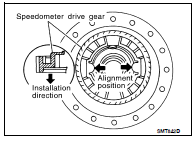
8. Align and install speedometer drive gear onto differential case.
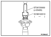
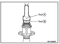
9. Press in differential side bearing (clutch housing side) to differential case using Tools (A) and (B).
Tool numbers A: ST30720000 (J-25405) B: KV38102510 ( — )
CAUTION: • Do not reuse differential side bearing and differential side bearing outer race.
• Replace differential side bearing and differential side bearing outer race as a set.
10. Install final gear into differential case and tighten final gear bolts to the specified torque.
Inspection
• Check the clearance between side gear and differential case as follows.
1. Clean final drive assembly sufficiently to prevent side gear thrust washer, differential case, side gear, and other parts from sticking by gear oil.
2. Put differential case vertically so that side gear to be measured faces upward.
3. Place Tool and a dial indicator onto side gear.
Tool number : — (J-39713)
4. Move side gear up and down, and measure the clearance.

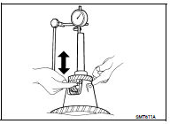
CAUTION: There should be no resistance and gears should rotate freely.
5. If not within specification, adjust the clearance by changing side gear thrust washer thickness.
6. Turn differential case upside down and measure the clearance between side gear and differential case on the other side in the same way.
INSPECTION AFTER DISASSEMBLY
Gear, Washer, Shaft, And Case
• Check side gears, side gear thrust washers, pinion mate shaft, pinion mate gears, pinion mate thrust washers and differential case. If necessary, replace with a new one.
Bearing
• Check for bearing damage and rough rotation. If necessary, replace with a new one. CAUTION: When replacing tapered roller bearing, replace outer and inner races as a set.
 Reverse idler shaft and gear
 Shift fork and fork rod