Nissan Altima (L32) 2007-2012 Service Manual: TEL Antenna
Removal and Installation - Coupe
REMOVAL
1. Remove the trunk front finisher, trunk floor carpet and spare tire cover.
Refer to INT-22, "Exploded View".
2. Remove the LH trunk floor spacer.
3. Remove the rear pillar LH. Refer to INT-20, "Exploded View".
4. Remove the rear parcel shelf. Refer to INT-17, "Removal and Installation".
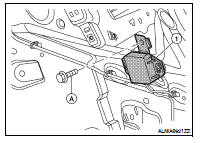
5. Remove the Bluetooth antenna screw (A), then detach the Bluetooth
antenna harness clips, disconnect the Bluetooth antenna
connector and remove the Bluetooth antenna (1).
INSTALLATION
Installation is in the reverse order of removal.
Removal and Installation - Sedan
REMOVAL
1. Remove the rear parcel shelf. Refer to INT-38, "Removal and Installation".
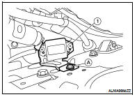
2. Remove the Bluetooth antenna screw (A), fold down the rear
seat, disconnect the Bluetooth antenna connector and remove
the Bluetooth antenna (1).
Removal and Installation
REMOVAL
1. Remove the room/map lamp assembly. Refer to INL-121, "Removal and
Installation".
2. Detach the microphone connector (A).
3. Remove the map lamp ...
Removal and Installation - Coupe
REMOVAL
1. Disconnect the battery negative terminal.
2. Remove the trunk floor carpet and spare tire cover. Refer to INT-22,
"Exploded View".
3. R ...
 Microphone
 Bluetooth control unit