Nissan Altima (L32) 2007-2012 Service Manual: Turn signal lamp circuit
Description
The BCM monitors inputs from the combination switch to determine when to activate the turn signals. The BCM outputs voltage direction to the left and right turn signals during turn signal operation or both during hazard warning operation. The BCM sends a turn signal indicator request to the combination meter via the CAN communication lines.
The BCM performs the fast flasher operation (fail-safe) if any bulb or harness of the turn signal lamp circuit is open.
NOTE: Turn signal lamp blinks at normal speed when using the hazard warning lamp.
Component Function Check
1.CHECK TURN SIGNAL LAMP

1. Select "FLASHER" of BCM (FLASHER) active test item.
2. With operating the test items, check that the turn signal lamp blinks.
Does the turn signal lamp blink? YES >> Turn signal lamp circuit is normal.
NO >> Refer to EXL-51, "Diagnosis Procedure".
Diagnosis Procedure
1.CHECK TURN SIGNAL LAMP BULB
Check the applicable lamp bulb to be sure the proper bulb standard is in use and the bulb is not open.
Is the bulb OK? YES >> GO TO 2
NO >> Replace the bulb.
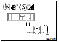
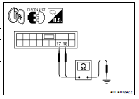
2.CHECK TURN SIGNAL LAMP OUTPUT VOLTAGE
1. Turn the ignition switch OFF.
2. Disconnect the front combination lamp connector, the door mirror connector and the rear combination lamp connector.
3. Turn the ignition switch ON.
4. With operating the turn signal switch, check the voltage between the BCM harness connector and the ground.
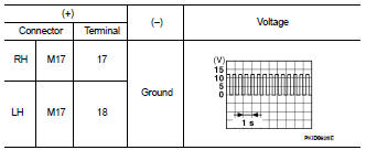
Is the measurement value normal? YES >> GO TO 3
NO >> Replace BCM. Refer to BCS-96, "Removal and Installation".
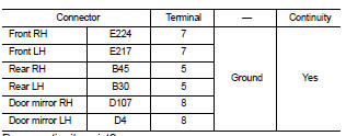
3.CHECK TURN SIGNAL LAMP CIRCUIT FOR OPEN
1. Turn the ignition switch OFF.
2. Disconnect BCM connector.
3. Check the continuity between the BCM harness connector and the front combination lamp, the rear combination lamp harness connector or the door mirror connector (if equipped with turn signals in mirrors).
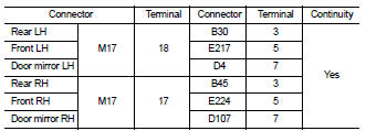
Does continuity exist? YES >> GO TO 4
NO >> Repair the harnesses or connectors.
4.CHECK TURN SIGNAL LAMP SHORT CIRCUIT
Check continuity between the BCM harness connector and the ground.
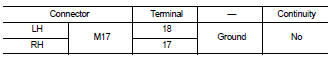
Does continuity exist? YES >> Repair the harnesses or connectors.
NO >> GO TO 5
5.CHECK TURN SIGNAL LAMP GROUND CIRCUIT
Check continuity between the front combination lamp, the rear combination lamp or the door mirror and ground (if equipped with turn signals in mirrors).
Does continuity exist? YES >> Replace the front combination lamp or the rear combination lamp.
NO >> Repair the harnesses or connectors.
 Parking lamp circuit
 Optical sensor