Nissan Altima (L32) 2007-2012 Service Manual: Optical sensor
Description
The optical sensor converts the outside brightness (lux) to voltage and transmits the optical sensor signal to the BCM.
Component Function Check
1.CHECK OPTICAL SENSOR SIGNAL BY CONSULT-III

1. Turn the ignition switch ON.
2. Select "OPTICAL SENSOR" of BCM (HEAD LAMP) DATA MONITOR item.
3. Turn the lighting switch to AUTO.
4. With the optical sensor illuminating, check the monitor status.
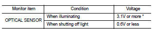
*: Illuminates the optical sensor. The value may be less than the standard value if brightness is weak.
Is the item status normal? YES >> Optical sensor is normal.
NO >> Refer to EXL-53, "Diagnosis Procedure".
Diagnosis Procedure
1.CHECK OPTICAL SENSOR POWER SUPPLY INPUT
1. Turn the ignition switch ON.
2. Turn the lighting switch to AUTO.
3. Check the voltage between the optical sensor harness connector and ground.
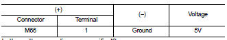
Is the voltage reading as specified? YES >> GO TO 2
NO >> GO TO 4
2.CHECK OPTICAL SENSOR GROUND INPUT
Check the voltage between the optical sensor harness connector and ground.
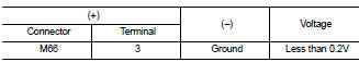
Is the voltage reading as specified? YES >> GO TO 3
NO >> GO TO 6
3.CHECK OPTICAL SENSOR SIGNAL OUTPUT
With the optical sensor illuminating, check voltage between the optical sensor harness connector and ground.
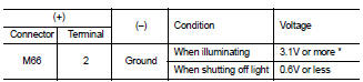
*: Illuminate the optical sensor. The value may be less than the standard if brightness is weak.
Is the voltage reading as specified? YES >> GO TO 7
NO >> Replace the optical sensor.
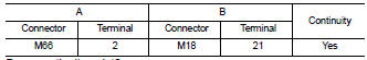
4.CHECK OPTICAL SENSOR POWER SUPPLY FOR OPEN CIRCUIT
1. Turn the ignition switch OFF.
2. Disconnect the optical sensor connector and BCM connector.
3. Check continuity between the optical sensor harness connector and the BCM harness connector.
Does continuity exist? YES >> GO TO 5
NO >> Repair the harnesses or connectors.
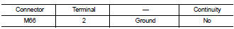
5.CHECK OPTICAL SENSOR POWER SUPPLY FOR SHORT CIRCUIT
Check the continuity between the optical sensor harness connector and the ground.
Does continuity exist? YES >> Repair the harnesses or connectors.
NO >> Replace BCM. Refer to BCS-96, "Removal and Installation" .6.CHECK OPTICAL SENSOR GROUND FOR OPEN CIRCUIT
1. Turn the ignition switch OFF.
2. Disconnect the optical sensor connector and BCM connector.
3. Check continuity between the optical sensor harness connector and the BCM harness connector.
Does continuity exist? YES >> Replace BCM. Refer to BCS-96, "Removal and Installation" .
NO >> Repair the harnesses or connectors.
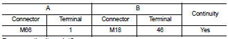
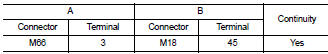
7.CHECK OPTICAL SENSOR SIGNAL FOR OPEN CIRCUIT
1. Turn the ignition switch OFF.
2. Disconnect the optical sensor connector and BCM connector.
3. Check continuity between the optical sensor harness connector and the BCM harness connector.
Does continuity exist? YES >> GO TO 8
NO >> Repair the harnesses or connectors.
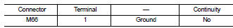
8.CHECK OPTICAL SENSOR SIGNAL FOR SHORT CIRCUIT
Check the continuity between the optical sensor harness connector and ground.
Does continuity exist? YES >> Repair the harnesses or connectors.
NO >> Replace BCM. Refer to BCS-96, "Removal and Installation"
 Turn signal lamp circuit
 Headlamp (halogen)