Nissan Altima (L32) 2007-2012 Service Manual: Variable induction air system
System Diagram
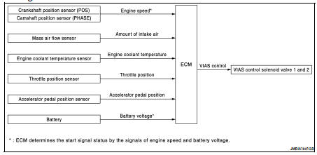
System Description
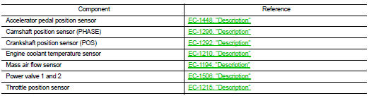
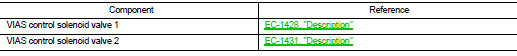
INPUT/OUTPUT SIGNAL CHART
*: ECM determines the start signal status by the signals of engine speed and battery voltage.
SYSTEM DESCRIPTION
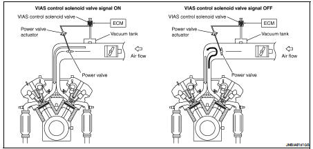
In the medium speed range, the ECM sends the ON signal to the VIAS control solenoid valve. This signal introduces the intake manifold vacuum into the power valve actuator and therefore closes the power valve.
Under this condition, the pressure waves of the exhaust stroke do not disturb the pressure waves of the intake stroke of each opposite bank. Therefore, charging efficiency is increased together with the effect of the long intake passage.
However, in the high speed range, the ECM sends the OFF signal to the VIAS control solenoid valve and the power valves is opened. Under this condition, the pressure waves of intake stroke are resonant with those of each opposite bank exhaust stroke. Therefore, charging efficiency is also increased.
In addition, both valves 1 and 2 are opened or closed in other ranges mentioned above. Thus maximum charging efficiency is obtained for the various driving conditions.
VACUUM HOSE DRAWING
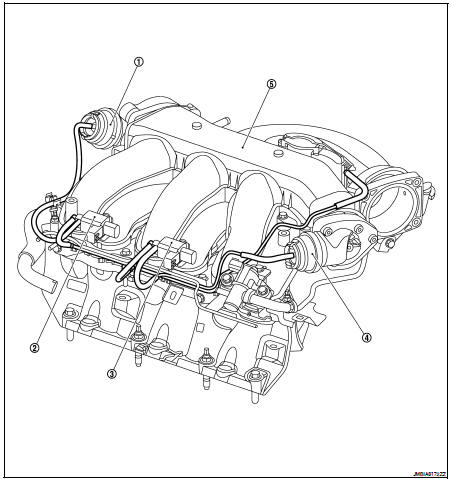
1. Power valve actuator 1
2. VIAS control solenoid valve 1
3. VIAS control solenoid valve 2
4. Power valve actuator 2
5. Intake manifold collector
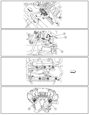
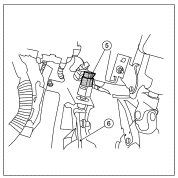
Component Parts Location
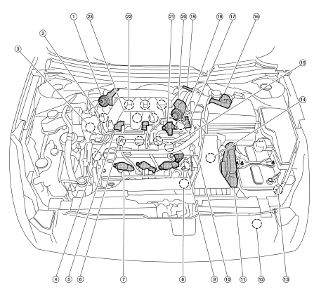
1. Power valve actuator 1
2. Intake valve timing control solenoid valve (bank 1)
3. Power steering pressure sensor
4. Intake valve timing control solenoid valve (bank 2)
5. VIAS control solenoid valves 1 and 2
6. Fuel injector (bank 2)
7. Ignition coil (with power transistor) and spark plug (bank 2)
8. Crankshaft position sensor (POS)
9. Engine coolant temperature sensor
10. Camshaft position sensor (PHASE) (bank 2)
11. ECM
12. Refrigerant pressure sensor
13. Battery current sensor
14. PNP switch
15. Condenser-2
16. Mass air flow sensor (with intake air temperature sensor)
17. EVAP service port
18. Camshaft position sensor (PHASE) (bank 1)
19. Electric throttle control actuator
20. Power valve actuator 2
21. EVAP canister purge volume control solenoid valve
22. Ignition coil (with power transistor) and spark plug (bank 1)
23. Knock sensor
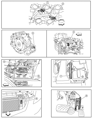
1. Mas air flow sensor (with intake air temperature sensor)
2. Air cleaner case
3. Engine coolant temperature sensor
4. EVAP canister purge volume control solenoid valve
5. Power valve actuator 1
6. VIAS control solenoid valve 1
7. VIAS control solenoid valve 2
8. Power valve actuator 2
9. Power steering pressure sensor
10. Tie rod (RH)
11. Power valve actuator 2
12. Camshaft position sensor (PHASE) (bank 1)
13. Camshaft position sensor (PHASE) (bank 2)

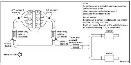
1. A/F sensor 1 (bank 1)
2. A/F sensor 1 (bank 2)
3. HO2S2 (bank 1) harness connector
4. HO2S2 (bank 2) harness connector (CVT models)
5. Front engine mount
6. HO2S2 (bank 2) harness connector (M/T models)
7. Crankshaft position sensor (POS) (M/T models)
8. Crankshaft position sensor (POS) (CVT models)

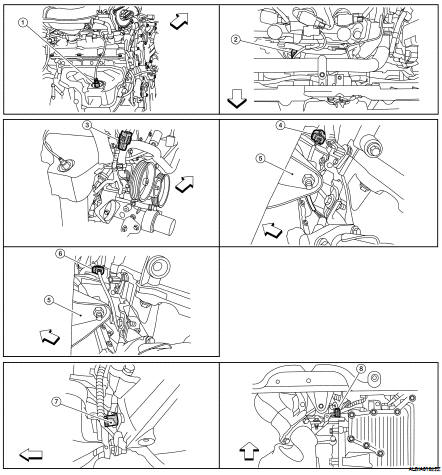
1. Electronic controlled engine mount control solenoid valve
2. EVAP control system pressure sensor
3. EVAP canister vent control valve
4. EVAP canister
5. Injector harness connector
6. Intake valve timing control solenoid valve (bank 1)
7. Intake valve timing control solenoid valve (bank 2)

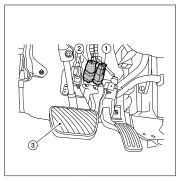
1. Knock sensor (bank 2)
2. Knock sensor (bank 1)
3. PNP switch (CVT models)
4. PNP switch (M/T models)
5. Battery
6. IPDM E/R
7. ECM
8. Refrigerant pressure sensor (shown with front grill removed)
9. Accelerator pedal

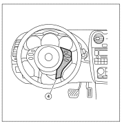
1. ASCD brake switch
2. Stop lamp switch
3. Brake pedal
4. ASCD steering switch
5. ASCD clutch switch (M/T models)
6. Clutch pedal
Component Description
 Intake valve timing control
 On board diagnostic (OBD) System