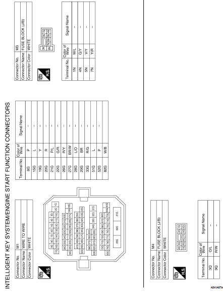
Nissan Altima (L32) 2007-2012 Service Manual: Wiring Diagram - Intelligent key system/
engine start function
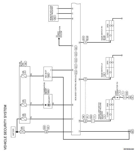
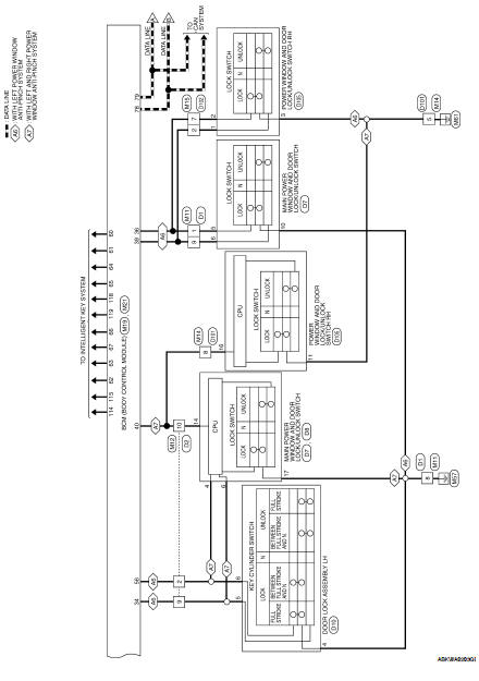
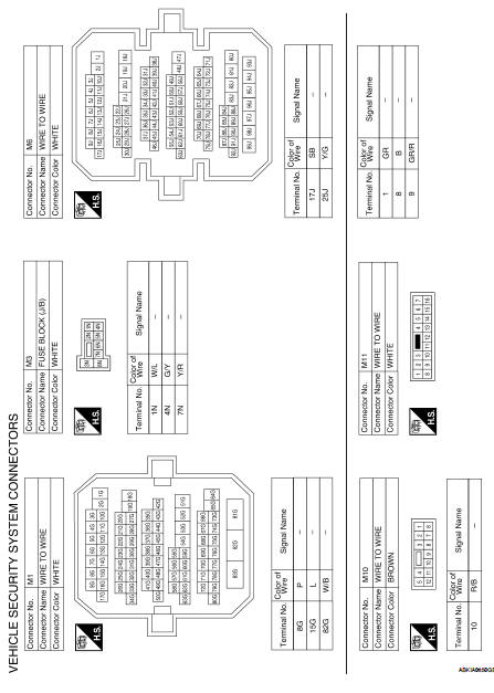
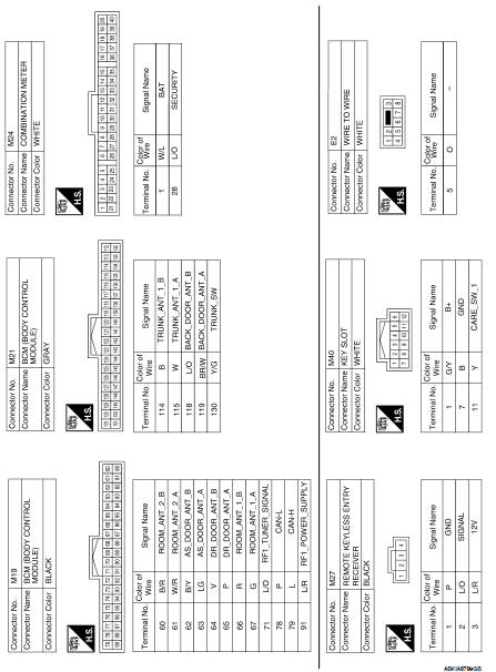
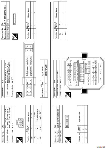
Wiring Diagram - VEHICLE SECURITY SYSTEM
Wiring Diagram - NVIS
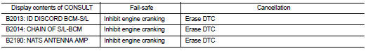
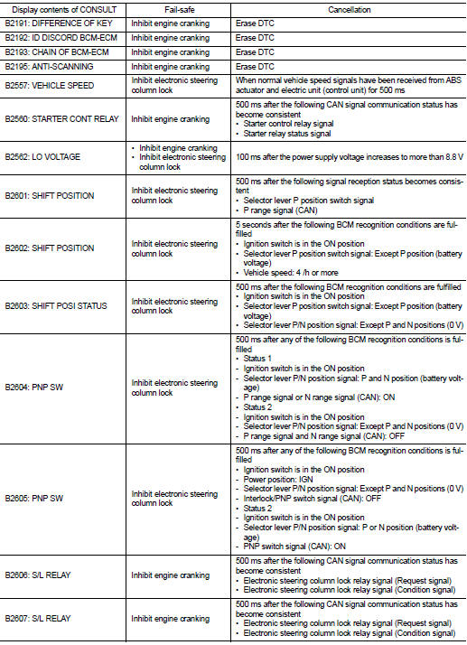
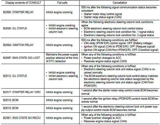
Fail Safe
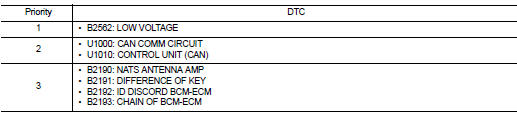
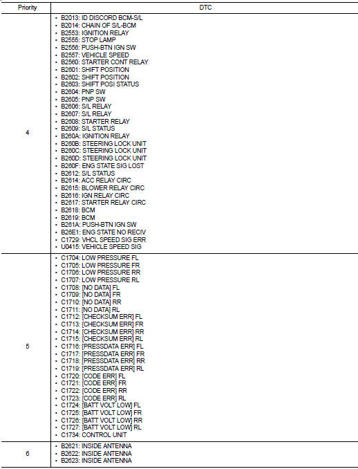
DTC Inspection Priority Chart
If some DTCs are displayed at the same time, perform inspections one by one
based on the following priority
chart.
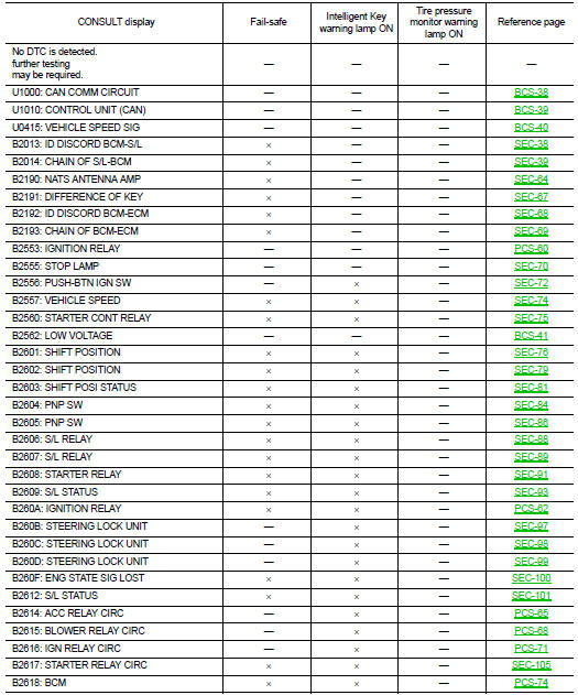
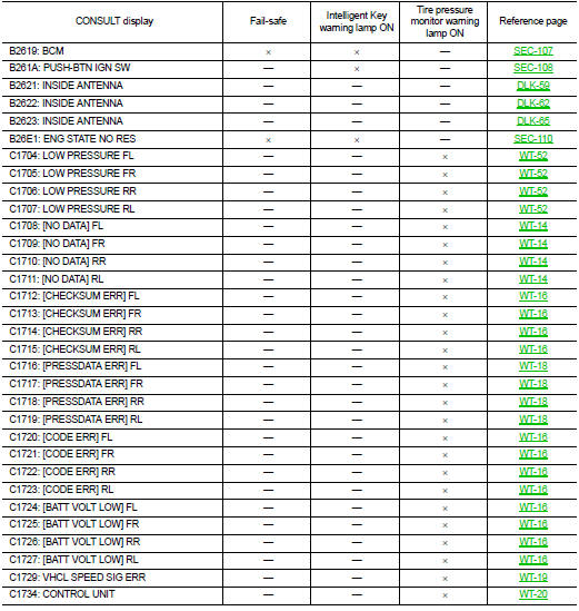
DTC Index
NOTE:
Details of time display
• CRNT: Displays when there is a malfunction now or after returning to the
normal condition until turning ignition
switch OFF → ON again.
• 1 - 39: Displayed if any previous malfunction is present when current
condition is normal. It increases like 1
→ 2 → 3...38 → 39 after returning to the normal condition whenever ignition
switch OFF → ON. The counter
remains at 39 even if the number of cycles exceeds it. It is counted from 1
again when turning ignition switch
OFF → ON after returning to the normal condition if the malfunction is detected
again.
Reference Value
VALUES ON THE DIAGNOSIS TOOL
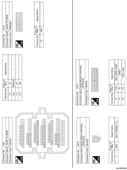
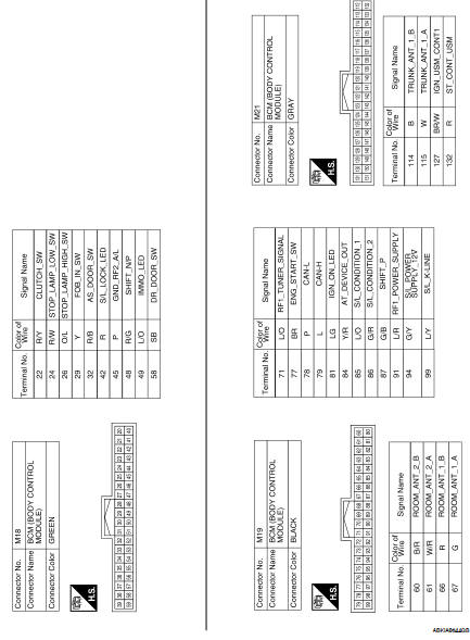
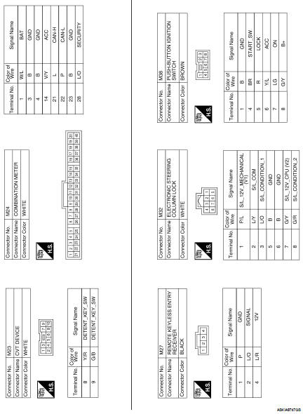
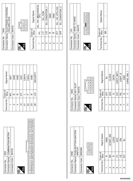
TERMINAL LAYOUT
PHYSICAL VALUES
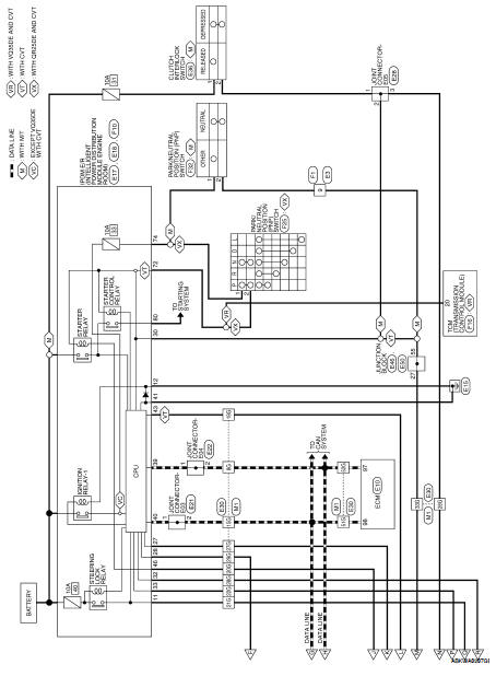
Wiring Diagram — Coupe
Fail Safe
CAN COMMUNICATION CONTROL
When CAN communication ...

 BCM (Body control module)
 IPDM E/R (Intelligent power distribution
module engine room)
IPDM E/R (Intelligent power distribution
module engine room)