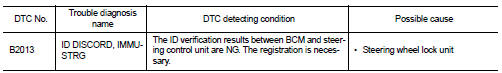
Nissan Altima (L32) 2007-2012 Service Manual: B2013 ID discord, immu-strg
Description
BCM performs the ID verification with the steering lock unit and releases the
steering lock if both BCM and
steering lock unit ID are same. BCM starts the communication with the steering
lock unit when Intelligent Key
is carried into the passenger compartment and the push-button ignition switch is
pressed.
DTC Logic
DTC DETECTION LOGIC
DTC CONFIRMATION PROCEDURE
1.PERFORM DTC CONFIRMATION PROCEDURE
1. Lock steering.
2. Press the push-button ignition switch.
3. Check “Self Diagnostic Result” with CONSULT-III.
Is DTC detected?
YES >> Refer to SEC-237, "Diagnosis Procedure".
NO >> Inspection End.
Diagnosis Procedure
1.PERFORM INITIALIZATION
Perform initialization with CONSULT-III. Re-register all Intelligent Keys.
For initialization and registration of Intelligent Key, refer to “CONSULT-III
Operation Manual”.
Can the system be initialized and can steering lock be released with
re-registered Intelligent Key?
YES >> Steering lock unit was unregistered.
Description
BCM performs the ID verification with the steering lock unit to release the
steering. BCM starts the communication
with the steering lock unit when Intelligent Key is carried into the ...
 U1010 control unit (can)
 B2014 chain of strg-immu