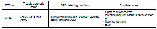
Nissan Altima (L32) 2007-2012 Service Manual: B2014 chain of strg-immu
Description
BCM performs the ID verification with the steering lock unit to release the steering. BCM starts the communication with the steering lock unit when Intelligent Key is carried into the passenger compartment and the pushbutton ignition switch is pressed.
DTC Logic
DTC DETECTION LOGIC
DTC CONFIRMATION PROCEDURE
1.PERFORM DTC CONFIRMATION PROCEDURE
1. Lock steering.
2. Press the push-button ignition switch.
3. Check “Self Diagnostic Result” with CONSULT-III.
Is DTC detected? YES >> Refer to SEC-238, "Diagnosis Procedure".
NO >> Inspection End.
Diagnosis Procedure
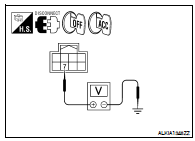
1.CHECK STEERING LOCK UNIT POWER SUPPLY
1. Turn ignition switch OFF.
2. Disconnect steering lock unit harness connector.
3. Check voltage between steering lock unit harness connector and ground while turning ignition switch from OFF to ACC.
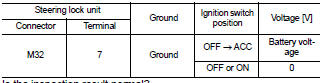
Is the inspection result normal? YES >> GO TO 3
NO >> GO TO 2
2.CHECK STEERING LOCK UNIT POWER SUPPLY CIRCUIT
1. Turn ignition switch OFF.
2. Disconnect BCM harness connector.
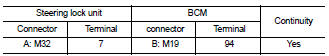
3. Check continuity between steering lock unit harness connector M32 (A) terminal 7 and BCM harness connector M19 (B) terminal 94.
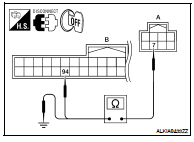
4. Check continuity between steering lock unit harness connector M32 (A) terminal 7 and ground.
Is the inspection result normal? YES >> GO TO 6
NO >> Repair harness or connector.
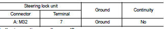
3.CHECK STEERING LOCK UNIT GROUND CIRCUIT
Turn ignition switch OFF.
2. Check continuity between steering lock unit and ground.
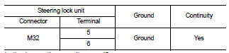
Is the inspection result normal? YES >> GO TO 4
NO >> Repair harness or connector.
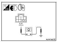
4.CHECK STEERING LOCK UNIT COMMUNICATION SIGNAL
1. Connect steering lock unit harness connector.
2. Using an oscilloscope, read voltage signal between steering lock unit harness connector and ground.
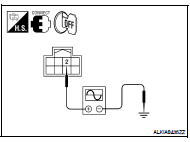
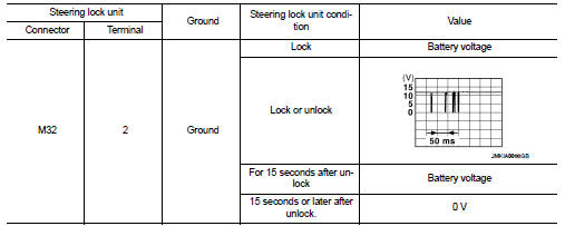

Is the inspection result normal? YES >> Replace steering lock unit.
NO >> GO TO 5
5.CHECK STEERING LOCK UNIT COMMUNICATION CIRCUIT
1. Turn ignition switch OFF.
2. Disconnect BCM harness connector.
3. Check continuity between BCM harness connector M19 (A) terminal 99 and steering lock unit harness connector M32 (B) terminal 2.
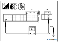
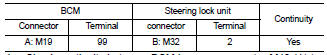
4. Check continuity between BCM harness connector M19 (A) terminal 99 and ground.
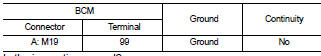
Is the inspection normal? YES >> GO TO 6
NO >> Repair harness or connector.
6.CHECK INTERMITTENT INCIDENT
Refer to GI-42, "Intermittent Incident".
>> Inspection End.
 B2013 ID discord, immu-strg
 B2108 steering lock relay