Nissan Altima (L32) 2007-2012 Service Manual: B210E starter relay
Description
Located in IPDM E/R, it runs the starter motor. The starter relay is turned ON by the BCM when the ignition switch is in START position. IPDM E/R transmits the starter relay ON signal to BCM via CAN communication.
DTC Logic
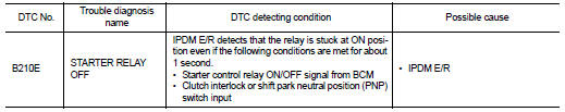
DTC DETECTION LOGIC
NOTE: • If DTC B210E is displayed with DTC U1000, first perform the trouble diagnosis for DTC U1000. Refer to SEC-235, "DTC Logic".
• If DTC B210E is displayed with DTC U1010, first perform the trouble diagnosis for DTC U1010. Refer to SEC-236, "DTC Logic".
DTC CONFIRMATION PROCEDURE
1.PERFORM DTC CONFIRMATION PROCEDURE
1. Turn ignition switch ON under the following conditions and wait for at least 1 second.
- CVT selector lever is in the P or N position
- Do not depress the brake pedal
2. Check “Self diagnostic result” with CONSULT-III.
Is DTC detected? YES >> Refer to SEC-250, "Diagnosis Procedure".
NO >> Inspection End.
Diagnosis Procedure
1.INSPECTION START
Check which type of transmission the vehicle is equipped with.
Which type of transmission
CVT >> GO TO 2
M/T >> GO TO 3
2.CHECK STARTER RELAY OUTPUT SIGNAL/CVT MODELS
1. Turn ignition switch OFF.
2. Disconnect BCM harness connector.
3. Check voltage between BCM harness connector and ground.
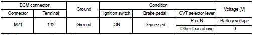
Is the inspection result normal? YES >> GO TO 5
NO >> GO TO 4
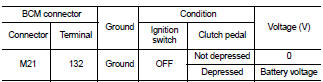
3.CHECK STARTER RELAY OUTPUT SIGNAL / M/T MODELS
1. Turn ignition switch OFF.
2. Disconnect BCM harness connector.
3. Check voltage between BCM harness connector and ground.
Is the inspection result normal? YES >> GO TO 5
NO >> GO TO 4
4.CHECK STARTER RELAY OUTPUT SIGNAL CIRCUIT
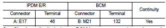
1. Disconnect IPDM E/R harness connector.
2. Check continuity between IPDM E/R harness connector and BCM harness connector.
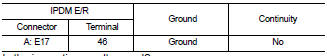
3. Check continuity between BCM harness connector and ground.
Is the inspection result normal? YES >> Replace IPDM E/R. Refer to PCS-48, "Removal and Installation".
NO >> Repair harness connector.
5.CHECK STARTER RELAY POWER SUPPLY CIRCUIT
1. Turn ignition switch OFF.
2. Disconnect IPDM E/R harness connector.
3. Check voltage between IPDM E/R harness connector and ground.
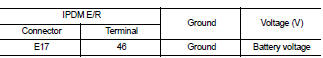
Is the inspection result normal? YES >> Replace IPDM E/R. Refer to PCS-48, "Removal and Installation".
NO >> Check harness for open or short between IPDM E/R and battery.
 B210D starter relay
 B210F PNP/clutch interlock switch