Nissan Altima (L32) 2007-2012 Service Manual: B2192, P1611 ID discord, immu-ecm
Description
BCM performs the ID verification with ECM that allows the engine to start. Start the engine if the ID is OK.
ECM prevents the engine from starting if the ID is not registered. BCM starts the communication with ECM if ignition switch is turned ON.
DTC Logic
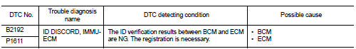
DTC DETECTION LOGIC
NOTE: • If DTC B2192 is displayed with DTC U1000, first perform the trouble diagnosis for DTC U1000. Refer to SEC-433, "DTC Logic".
• If DTC B2192 is displayed with DTC U1010, first perform the trouble diagnosis for DTC U1010. Refer to SEC-434, "DTC Logic".
DTC CONFIRMATION PROCEDURE
1.PERFORM DTC CONFIRMATION PROCEDURE
1. Turn ignition switch ON under the following conditions: - CVT selector lever is in the P or N position.
- Do not depress the brake pedal.
2. Check “Self Diagnostic Result” with CONSULT-III.
Is DTC detected? YES >> Refer to SEC-459, "Diagnosis Procedure".
NO >> Inspection End.
Diagnosis Procedure
1.PERFORM INITIALIZATION
Perform initialization with CONSULT-III. Re-register all keyfobs.
For initialization and registration of keyfob, refer to CONSULT-III Operation Manual.
Can the system be initialized and can the engine be started with re-registered keyfob? YES >> ID was unregistered.
NO >> BCM is malfunctioning.
• Replace BCM. Refer to BCS-96, "Removal and Installation".
• Perform initialization again.
• Replace ECM.
 B2191, P1615 Difference of key
 B2193, P1612 chain of ECM-IMMU