Nissan Altima (L32) 2007-2012 Service Manual: B2604 PNP switch
Description
BCM confirms the shift position with the following 4 signals.
• CVT selector lever
• P/N position switch
• P position signal from IPDM E/R (CAN)
• P position signal from TCM (CAN)
DTC Logic
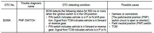
DTC DETECTION LOGIC
NOTE: • If DTC B2604 is displayed with DTC U1000, first perform the trouble diagnosis for DTC U1000. Refer to SEC-433, "DTC Logic".
• If DTC B2604 is displayed with DTC U1010, first perform the trouble diagnosis for DTC U1010. Refer to SEC-434, "DTC Logic".
DTC CONFIRMATION PROCEDURE
1.PERFORM DTC CONFIRMATION PROCEDURE
1. Start the engine under the following conditions and wait for at least 1 second.
- CVT selector lever is in the P position
- Do not depress the brake pedal
2. Use CVT selector lever to select each gear one at a time. Wait at each gear for at least 1 second.
3. Check “Self diagnostic result” with CONSULT-III.
Is DTC detected? YES >> Refer to SEC-475, "Diagnosis Procedure".
NO >> Inspection End.
Diagnosis Procedure
1.CHECK DTC WITH TCM
Check “Self diagnostic result” with CONSULT-III. Refer to TM-399, "DTC Index".
Is the inspection result normal? YES >> GO TO 2
NO >> Repair or replace malfunctioning parts.
2.CHECK PNP SWITCH CIRCUIT
1. Turn ignition switch OFF.
2. Disconnect TCM harness connector and BCM harness connector.
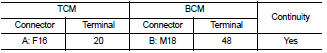
3. Check continuity between TCM harness connector and BCM harness connector.
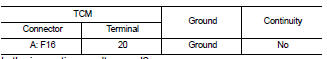
4. Check continuity between TCM harness connector and ground.
Is the inspection result normal? YES >> GO TO 3
NO >> Repair harness or connector.
3.CHECK INTERMITTENT INCIDENT
Refer to GI-42, "Intermittent Incident".
>> Inspection End.
 B2603 shift position status
 B2605 PNP switch