Nissan Altima (L32) 2007-2012 Service Manual: B2607 steering lock relay
Description
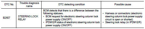
BCM requests to IPDM E/R to supply power to electronic steering column lock. IPDM E/R sends status of electronic steering column lock back to BCM.
DTC Logic
DTC DETECTION LOGIC
NOTE: • If DTC B2607 is displayed with DTC U1000, first perform the trouble diagnosis for DTC U1000. Refer to SEC-235, "DTC Logic".
• If DTC B2607 is displayed with DTC U1010, first perform the trouble diagnosis for DTC U1010. Refer to SEC-236, "DTC Logic".
DTC CONFIRMATION PROCEDURE
1.PERFORM DTC CONFIRMATION PROCEDURE
1. Press the push-button ignition switch under the following conditions.
- CVT selector lever is in the P position
- Do not depress brake pedal 2. Steering lock is locked.
3. Check “Self diagnostic result” with CONSULT-III.
Is DTC detected? YES >> Refer to SEC-288, "Diagnosis Procedure".
NO >> Inspection End.
Diagnosis Procedure
1.CHECK DTC WITH IPDM E/R
Check “Self diagnostic result” with CONSULT-III. Refer to PCS-45, "DTC Index".
Is the inspection result normal? YES >> GO TO 2
NO >> Repair or replace malfunctioning parts.
2.CHECK ELECTRONIC STEERING COLUMN LOCK POWER SUPPLY CIRCUIT
1. Turn ignition switch OFF.
2. Disconnect electronic steering column lock harness connector.
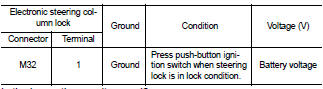
3. Check voltage between electronic steering column lock and ground under the following conditions.
Is the inspection result normal?
YES >> GO TO 4
NO >> GO TO 3
3.CHECK ELECTRONIC STEERING COLUMN LOCK POWER SUPPLY CIRCUIT
1. Turn ignition switch OFF.
2. Disconnect IPDM E/R harness connector.
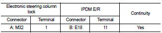
3. Check continuity between electronic steering column lock and IPDM E/R harness connector.
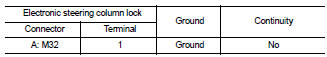
4. Check continuity between electronic steering column lock and ground.
Is the inspection result normal? YES >> Replace IPDM E/R. Refer to PCS-48, "Removal and Installation".
NO >> Repair harness or connector.
4.CHECK INTERMITTENT INCIDENT
Refer to GI-42, "Intermittent Incident".
>> Inspection End.
 B2606 steering lock relay
 B2608 starter relay