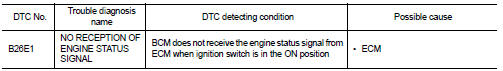
Nissan Altima (L32) 2007-2012 Service Manual: B26E1 No reception of engine status
signal
Description
BCM receives the engine status signal from ECM via CAN communication.
DTC Logic
DTC DETECTION LOGIC
NOTE:
• If DTC B26E1 is displayed with DTC U1000, first perform the trouble diagnosis
for DTC U1000. Refer to
SEC-235, "DTC Logic".
• If DTC B26E1 is displayed with DTC U1010, first perform the trouble diagnosis
for DTC U1010. Refer to
SEC-236, "DTC Logic".
DTC CONFIRMATION PROCEDURE
1.PERFORM DTC CONFIRMATION PROCEDURE
1. Turn ignition switch ON under the following conditions.
- CVT selector lever is in the P or N position.
- Do not depress the brake pedal.
2. Check “Self diagnostic result” with CONSULT-III.
Is DTC detected?
YES >> Refer to SEC-309, "Diagnosis Procedure".
NO >> Inspection End.
Diagnosis Procedure
1.INSPECTION START
1. Turn ignition switch ON.
2. Check “Self diagnostic result” with CONSULT-III.
3. Touch “ERASE”.
4. Perform DTC Confirmation Procedure.
See SEC-309, "DTC Logic".
Is the DTC B26E1 displayed again?
YES >> GO TO 2
NO >> Inspection End.
2.REPLACE ECM
1. Replace ECM.
2. Refer to EC-1048, "BASIC INSPECTION : Special Repair Requirement" (VQ35DE),
EC-560, "BASIC
INSPECTION : Special Repair Requirement" (QR25DE except California), EC-24,
"BASIC INSPECTION :
Special Repair Requirement" (QR25DE California).
>> Inspection End.
Description
IPDM E/R transmits the push-button ignition switch status via CAN
communication to BCM. BCM receives
push-button ignition switch status by hardwire input. BCM compares the 2 signals
...
BCM
Diagnosis Procedure
1. CHECK FUSE AND FUSIBLE LINK
Check if the following BCM fuse or fusible link are blown.
Is the fuse or fusible link blown?
YES >> Replace the blown fuse or fus ...
Other materials: Tachometer
5 inch (13 cm) Type A (if so equipped)
The tachometer indicates engine speed in
revolutions per minute (rpm).
Do not rev the engine into the red zone 1.
7 inch (18 cm) Type B (if so equipped)
CAUTION
When engine speed approaches the
red zone, shift to a higher gear or reduce
engine speed. Operati ...
Supplemental air bag warning labels
Warning labels about the supplemental
front-impact air bag system are placed in
the vehicle as shown in the illustration.
WARNING
Do not use a rear-facing child restraint
on a seat protected by an air bag in
front of it. If the air bag deploys, it may
cause serious injury or death.
Supplemental air ...
Resetting the drive computer
The drive computer is divided across three
screens:
Speed
Trip Distance & Time
Fuel Economy
1. Press the or
buttons until the
desired drive computer screen is
displayed.
2. Press the OK button to bring up the drive
computer Reset menu.
3. Use the or
to select the desired
option. Then press ...
 B261A push-button ignition switch
 POWER supply and ground circuit