Nissan Altima (L32) 2007-2012 Service Manual: POWER supply and ground circuit
BCM
Diagnosis Procedure
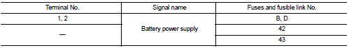
1. CHECK FUSE AND FUSIBLE LINK
Check if the following BCM fuse or fusible link are blown.
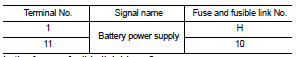
Is the fuse or fusible link blown? YES >> Replace the blown fuse or fusible link after repairing the affected circuit.
NO >> GO TO 2
2. CHECK POWER SUPPLY CIRCUIT
1. Turn ignition switch OFF.
2. Disconnect BCM.
3. Check voltage between BCM harness connector and ground.
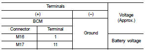
Is the measurement normal? YES >> GO TO 3
NO >> Repair or replace harness.
3. CHECK GROUND CIRCUIT
Check continuity between BCM harness connector and ground.
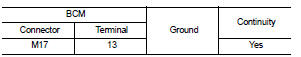
Does continuity exist? YES >> Inspection End.
NO >> Repair or replace harness.
Special Repair Requirement
1. REQUIRED WORK WHEN REPLACING BCM
Initialize control unit. Refer to BCS-6, "CONFIGURATION (BCM) : Special Repair Requirement".
>> Work End.
IPDM E/R (INTELLIGENT POWER DISTRIBUTION MODULE ENGINE ROOM)
Diagnosis Procedure
1. CHECK FUSES AND FUSIBLE LINK
Check that the following IPDM E/R fuses or fusible link are not blown.
Is the fuse blown? YES >> Replace the blown fuse or fusible link after repairing the affected circuit.
NO >> GO TO 2
2. CHECK POWER SUPPLY CIRCUIT
1. Turn ignition switch OFF.
2. Disconnect IPDM E/R connectors.
3. Check voltage between IPDM E/R harness connector and ground.
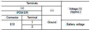
Is the measurement value normal? YES >> GO TO 3
NO >> Repair harness or connector.
3. CHECK GROUND CIRCUIT
Check continuity between IPDM E/R harness connectors and ground.
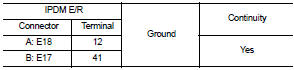
Does continuity exist? YES >> Inspection End.
NO >> Repair harness or connector.
 B26E1 No reception of engine status
signal
B26E1 No reception of engine status
signal Key slot