Nissan Altima (L32) 2007-2012 Service Manual: Clutch master cylinder
Removal and Installation
REMOVAL
1. Remove the air cleaner and air duct. Refer to EM-19, "Removal and Installation" for QR25DE and EM- 123, "Removal and Installation" for VQ35DE.
2. Use one of the following methods to remove hose from master cylinder.
• Drain clutch fluid from reservoir tank and remove hose.
• Remove hose from master cylinder. Immediately plug hose and reservoir tank to prevent clutch fluid from dripping.
CAUTION: Do not spill clutch fluid onto painted surfaces. If it spills, wipe up immediately and wash the affected area with water. 3. Remove master cylinder rod end from clutch pedal assembly.
4. Remove lock pin (1) from connector of master cylinder (2) and separate clutch tube (3).
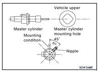
5. Rotate master cylinder clockwise by 45° and remove from the vehicle.
INSTALLATION
1. Tilt master cylinder clockwise by 45° and insert it in the mounting hole. Rotate counterclockwise to secure it. At this time, nipple is in the up position.
2. Install master cylinder rod end to clutch pedal.
3. Install clutch tube (1) fully into connector of master cylinder (2).
4. Install lock pin (3) fully into connector of master cylinder (2).
5. Fill with new clutch fluid and bleed clutch hydraulic system.
Refer to CL-6, "Inspection and Adjustment".
6. Inspect clutch pedal operation. Refer to CL-6, "Inspection and Adjustment".
7. Install the air cleaner and air duct. Refer to EM-19, "Removal and Installation" for QR25DE and EM-123, "Removal and Installation" for VQ35DE.
 Clutch pedal
 Clutch piping