Nissan Altima (L32) 2007-2012 Service Manual: Cylinder head
Removal and Installation
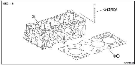
1. Cylinder head
2. Cylinder head gasket
3. Cylinder head bolt
A. Follow installation procedure
REMOVAL
1. Remove the engine and transaxle assembly. Refer to EM-72, "Removal and Installation".
2. Remove the timing chain. Refer to EM-52, "Removal and Installation".
3. Remove the camshafts. Refer to EM-41.
4. Remove spark plugs. Refer to EM-14, "Removal and Installation".
5. Remove the exhaust manifold and three way catalyst. Refer to EM-30, "Removal and Installation".
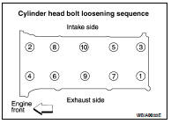
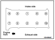
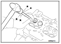
6. Remove cylinder head loosening bolts in the order as shown, using power tool.
7. If necessary to transfer to new cylinder head or remove for reconditioning, remove the intake manifold collector, intake manifold, and fuel tube assembly. Refer to EM-66, "Disassembly and Assembly".
INSPECTION AFTER REMOVAL
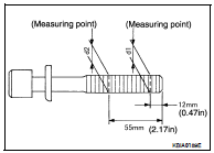
Outer Diameter of Cylinder Head Bolts
• Cylinder head bolts are tightened by plastic zone tightening method. Whenever the size difference between d1 and d2 exceeds the limit, replace the bolts with new ones.
Limit (d1 - d2) : 0.23 mm (0.0091 in) or less
• If reduction of outer diameter appears in a position other than d2, use it as d2 point.
INSTALLATION
1. Install a new cylinder head gasket.
2. Install the cylinder head.
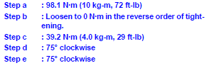
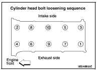
3. Follow the steps below to tighten the cylinder head bolts in the numerical order as shown.
• Apply new engine oil to the threads and the seating surfaces of bolts.
CAUTION: • If cylinder head bolts are re-used, check their outer diameters before installation. Follow the Outer Diameter of Cylinder Head Bolts measurement procedure.
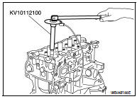
• Check and confirm the tightening angle by using angle wrench or protractor. Avoid judgment by visual inspection without the tool.
Tool number : KV10112100 (BT-8653-A)
4. Installation of the remaining components is in the reverse order of removal.
Disassembly and Assembly
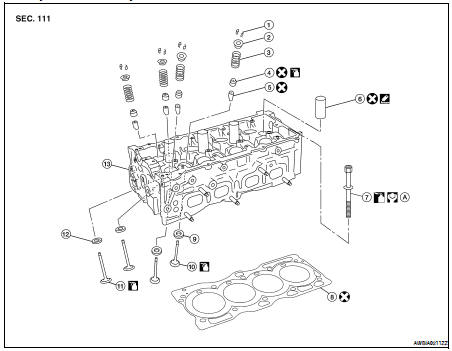
1. Valve collet
2. Valve spring retainer
3. Valve spring
4. Valve oil seal
5. Valve guide
6. Spark plug tube
7. Cylinder head bolt
8. Cylinder head gasket
9. Valve seat (EXH)
10. Valve (EXH)
11. Valve (INT)
12. Valve seat (INT)
13. Cylinder head
A. Follow installation procedure
CAUTION: • When installing camshafts, chain tensioners, oil seals or other sliding parts, lubricate contacting surfaces with new engine oil.
• Apply new engine oil to threads and seat surfaces when installing the cylinder head, camshaft sprocket, crankshaft pulley and camshaft bracket.
• Attach tags to valve lifters so all parts are assembled in their original position.
DISASSEMBLY
1. Remove the valve lifter.
• Confirm installation point.
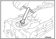
2. Remove the valve collet, valve spring retainer and valve spring using Tool.
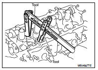
CAUTION: Do not remove valve spring seat from valve spring.
3. Push valve stem to combustion chamber side, and remove valve.
• Inspect valve guide clearance before removal. Refer to EM- 68, "Inspection After Disassembly".
Confirm installation point.
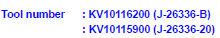
4. Remove valve oil seal using Tool.
Tool number : KV10107902 (J-38959)
5. When valve seat must be replaced, refer to EM-68, "Inspection After Disassembly".
6. When valve guide must be replaced, refer to EM-68, "Inspection After Disassembly".
7. Remove spark plug using suitable tool.
8. Remove spark plug tubes, if necessary using suitable tool.
CAUTION: • Be careful not to damage cylinder head.
• Do not remove spark plug tube if not necessary. Once removed, the spark plug tube cannot be reused because of deformation during removal.
ASSEMBLY
1. Install valve guide. Refer to EM-68, "Inspection After Disassembly".
2. Install valve seat. Refer to EM-68, "Inspection After Disassembly".
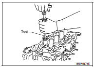
3. Install new valve oil seal using Tool as shown.
Oil seal installed height (A) : 12.1 mm (0.476 in)
Tool number : KV10115600 (J-38958)
4. Install valve.
• Install larger diameter to intake side.
5. Install valve spring.
• Install valve spring so that the identification color faces upwards.
• Confirm the identification color of the valve spring.
• Intake: pink
• Exhaust: green
6. Install valve spring retainer.
7. Install valve collet using Tool.
• Compress valve spring with valve spring compressor. Install valve collet with magnet hand.
• Tap stem edge lightly with plastic hammer after installation to check its installed condition.
8. Install valve lifter.
9. Install spark plug tube.
a. Remove old liquid gasket from cylinder head side mounting hole.
b. Apply liquid gasket all around on spark plug tube with a 12 mm (0.47 in) width from edge of spark plug tube on the press fit side.
• Use Three Bond or equivalent. Refer to GI-15, "Recommended Chemical Products and Sealants".
c. Press fit spark plug tube so that height is to (H) as shown.
Press fit height (H) standard value : 41.7 mm (1.642 in)
CAUTION: • When press fitting be careful not to deform spark plug tube.
• After press fitting, wipe off any protruding liquid gasket on top surface of cylinder head.
10. Install spark plug using suitable tool.
Inspection After Disassembly
CYLINDER HEAD DISTORTION
1. Wipe off oil and remove water scale deposits, old gasket, old sealer, and carbon with a scraper.
CAUTION: Use care not to allow gasket debris to enter passages for oil or water.
2. At each of several locations on bottom surface of cylinder head, measure distortion in six directions.
Limit : 0.1 mm (0.004 in)
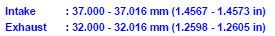
VALVE DIMENSIONS
Check dimensions of each valve. Refer to EM-99, "Standard and Limit".
VALVE GUIDE CLEARANCE
• Measure diameter of valve stem using suitable tool (A) as shown.
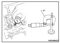
• Measure inner diameter of valve guide with a bore gauge as shown.

• Valve guide clearance = (Valve guide inner diameter) - (Valve stem diameter)
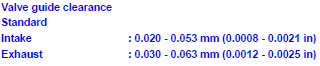
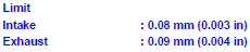
• If it exceeds the limit, replace valve guide and/or valve. When valve guide must be replaced, follow the "VALVE GUIDE REPLACEMENT" procedure.
VALVE GUIDE REPLACEMENT
When valve guide is removed, replace with oversized (0.2 mm, 0.008 in) valve guide.
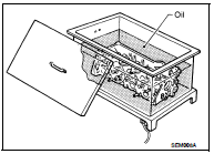
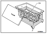
1. To remove valve guide, heat cylinder head to 110° to 130°C (230° to 266°F) by soaking in heated oil.
2. Drive out valve guide with a press [under a 20 kN (2.2 ton-force) pressure] or hammer and suitable tool.
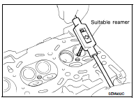
3. Ream cylinder head valve guide hole using suitable reamer.

4. Heat cylinder head to 110° to 130°C (230° to 266°F) by soaking in heated oil.
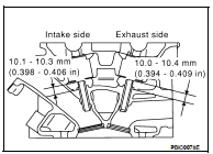
5. Press valve guide from camshaft side to dimensions as shown.
6. Apply finish to valve guide using suitable reamer.

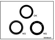
VALVE SEAT CONTACT
NOTE: After confirming that the dimensions of valve guides and valves are within specifications, perform this procedure: • Apply prussian blue (or white lead) onto contacting surface of valve seat to check the condition of the valve contact on the seat surface.
• Check if the contact area band is continuous all around the circumference.
• If not, grind to adjust valve fitting and check again. If the contacting surface still has NG conditions even after the re-check, replace the valve seat.
VALVE SEAT REPLACEMENT
NOTE: When valve seat is removed, replace with an oversized [0.5 mm (0.020 in)] valve seat.
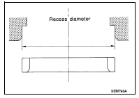
1. Bore out old seat until it collapses. Boring should not continue beyond the bottom face of the seat recess in the cylinder head. Set the machine depth stop to ensure this.
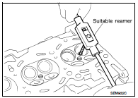
2. Ream cylinder head recess diameter for service valve seat.
• Be sure to ream in circles concentric to the valve guide center.
This will enable the valve seat to fit correctly.
3. Heat cylinder head to 110° to 130°C (230° to 266°F) by soaking in heated oil.
4. Use valve seats cooled well with dry ice. Force fit valve seat into cylinder head.
CAUTION: Avoid directly touching the cold valve seats.
5. Finish the seat to the specified dimensions using suitable tool.
Refer to EM-99, "Standard and Limit".
CAUTION: When using valve seat cutter, firmly grip the cutter handle with both hands. Then, press on the contacting surface all around the circumference to cut in a single drive. Improper pressure on the cutter or cutting many different times may result in a defective valve seat.
6. Using compound, grind to adjust valve fitting.
7. Check again for normal contact.
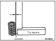
VALVE SPRING SQUARENESS
Set try square along the side of the valve spring and rotate the spring. Measure the maximum clearance between the top face of the spring and the try square.
Limit : 1.9 mm (0.0748 in)
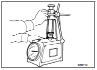
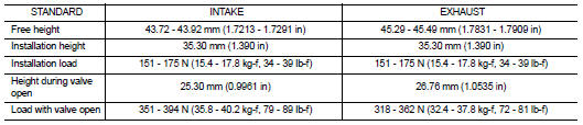
VALVE SPRING DIMENSIONS AND VALVE SPRING PRESSURE LOAD
Check valve spring pressure with valve spring seat installed at specified spring height. Replace if not within specifications.
CAUTION: Do not remove the valve spring seat.
Removal and installation
ENGINE ASSEMBLY
Removal and Installation
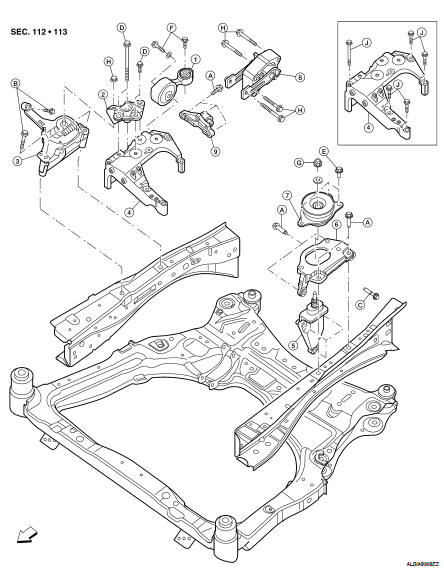
1. RH engine mount torque rod
2. RH engine support bracket
3. RH engine mounting insulator
4. RH engine mounting bracket
5. Transmission mounting bracket
6. LH engine mounting bracket
7. LH engine mounting insulator
8. Rear engine mount torque rod
9. Rear engine mount torque rod bracket
A. 40 N·m (4.1 kg-m, 30 ft-lb)
B. 41 N·m (4.2 kg-m, 30 ft-lb)
C. 45 N·m (4.6 kg-m, 33 ft-lb)
D. 50 N·m (5.1 kg-m, 37 ft-lb)
E. 60 N·m (6.1 kg-m, 44 ft-lb)
F. 85 N·m (8.7 kg-m, 63 ft-lb)
G. 90 N·m (9.2 kg-m, 66 ft-lb)
G. 90 N·m (9.2 kg-m, 66 ft-lb)
J. Follow installation procedure

WARNING: • Place chocks at the front and back of the rear wheels.
• For engines not equipped with slingers, attach proper slingers and bolts as described in the Parts Catalog.
CAUTION: • Do not start working until the exhaust system and coolant are cool.
• If items or work required are not covered by the engine main body section, follow the applicable procedures.
• Use the correct supporting points for lifting and jacking. Refer to GI-33, "Garage Jack and Safety Stand".
• In removing the drive shaft, be careful not to damage the grease seals on the transaxle.
REMOVAL
1. Remove engine cover using power tool.
2. Release fuel pressure. Refer to EC-550, "Inspection" (California), EC-1038, "Inspection" (Except California).
3. Disconnect the negative battery terminal. Refer to PG-68, "Removal and Installation" (Coupe models), PG-139, "Removal and Installation" (Sedan models).
4. Disconnect the fuel rail at the fuel hose quick connector (engine side). Refer to EM-26 .
5. Drain the engine oil. Refer to LU-10, "Changing Engine Oil".
6. Drain the engine coolant. Refer to CO-12, "Changing Engine Coolant".
7. Remove the engine undercover using power tools.
8. Drain power steering fluid. Refer to ST-8, "Draining".
9. Drain transaxle fluid. Refer to TM-17, "Draining" (M/T), TM-417, "Changing CVT Fluid" (CVT).
10. Remove hood assembly. Refer to DLK-208, "HOOD ASSEMBLY : Removal and Installation".
11. Remove the air duct and air cleaner case assembly. Refer to EM-25, "Removal and Installation".
12. Remove battery tray.
13. Remove the ECM bracket.
14. Remove cowl top. Refer to EXT-18, "Removal and Installation" (Coupe models), EXT-39, "Removal and Installation" (Sedan models).
15. Remove strut brace. Refer to FSU-12, "Exploded View".
16. Disconnect and set aside the IPDM/ER and remove the IPDM/ER bracket. Refer to PCS-48, "Removal and Installation".
17. Remove upper and lower radiator hoses (engine side) 18. Remove CVT cooler lines (CVT models).
19. Disconnect fuel lines 20. Remove the engine coolant reservoir tank.
21. Disconnect the heater hoses.
22. Remove front LR and RH wheels and tires. Refer to WT-66, "Adjustment".
23. Remove the engine under covers and splash shield using power tool.
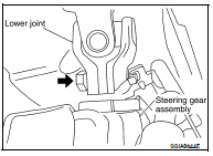
24. Remove the lower side bolt of the lower steering shaft assembly.
25. Remove rear cover plate.
26. Remove the torque converter bolts (CVT models).
27. Remove the rear engine mount torque rod.
28. Remove front exhaust tube. Refer to EX-5, "Exploded View".
29. Remove the left and right drive shafts. Refer to FAX-11, "Removal and Installation (Left Side)", FAX-12, "Removal and Installation (Right Side)".
30. Remove the front suspension member. Refer to FSU-13, "Removal and Installation".
31. Dismount the A/C compressor with piping connected and secure with wire to the radiator support.
32. Dismount the power steering pump with piping connected and position it aside with wire.
33. Disconnect the clutch operating cylinder fluid line (M/T models). Refer to CL-12, "Removal and Installation".
34. Disconnect the transaxle shift controls.
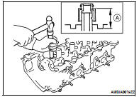
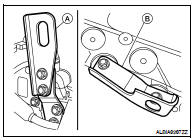
35. Install engine slingers into front left cylinder head (A) and rear right cylinder head (B).
• Use generator bracket bolt holes for the front slinger.
• Use the proper slingers and bolts as described in the Parts Catalog.
Slinger bolts - front : 48 N·m (4.9 kg-m, 35 ft-lb)
Slinger bolts - rear : 28 N·m (2.8 kg-m, 21 ft-lb)
36. Support engine and transaxle assembly with engine lifting equipment from the top with the vehicle raised on a hoist.
37. Remove the RH engine mount torque rod, RH engine support bracket and RH engine mounting insulator and bracket.
38. Remove LH transaxle mounting insulator through-bolts.
39. Lower the engine and transaxle assembly from the engine compartment using suitable tool.
CAUTION: • Before and during this procedure, always check if any harnesses are left connected.
• Avoid any damage to, or any oil/grease smearing or spills onto the engine mounting insulators.
40. Remove the starter motor. Refer to STR-25, "Removal and Installation" (M/T), STR-25, "Removal and Installation" (CVT).
41. Separate engine and transaxle. Refer to TM-26, "Exploded View" (M/T), TM-447, "Exploded View" (CVT).
INSTALLATION Installation is in the reverse order of removal.
NOTE: Tighten the transmission mounting bolts to specification. Refer to TM-26, "Removal and Installation" (M/T), TM-447, "Removal and Installation" (CVT).
• Do not allow oil to get on mounting insulators. Be careful not to damage mounting insulators.
• If parts have a direction mark (arrow) this indicates front of the vehicle, and the parts must be installed according to the identification mark.
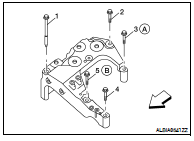
• Install the RH engine mounting bracket bolts in the following steps: - First install bolts (A) and (B) loosely.
- Install and tighten the five RH engine mounting bracket bolts to specification in the order as shown.
RH engine mounting bracket bolt : 48.2 N·m (4.9 kg-m, 36 ft-lb)

INSPECTION AFTER INSTALLATION
Before starting engine, check oil/fluid levels including engine coolant and engine oil. If less than required quantity, fill to the specified level. Refer to MA-12, "Fluids and Lubricants".
• Use procedure below to check for fuel leakage.
• Turn ignition switch ON (with engine stopped). With fuel pressure applied to fuel piping, check for fuel leakage at connection points.
• Start engine. With engine speed increased, check again for fuel leakage at connection points.
• Run engine to check for unusual noise and vibration.
• Warm up engine thoroughly to make sure there is no leakage of fuel, exhaust gas, or any oils/fluids including engine oil and engine coolant.
• Bleed air from passages in lines and hoses, such as in cooling system.
• After cooling down engine, again check oils/fluids including engine oil and engine coolant. Refill to specified level, if necessary.
• Summary of the inspection items:
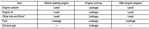
*Transmission/transaxle/CVT fluid, power steering fluid, brake fluid, etc.
 Oil seal
 Disassembly and assembly