Nissan Altima (L32) 2007-2012 Service Manual: Oil seal
Removal and Installation of Valve Oil Seal
REMOVAL
1. Remove camshaft. Refer to EM-41, "Removal and Installation".
2. Remove valve lifter. Refer to EM-41, "Removal and Installation".
3. Rotate crankshaft, and set piston whose oil seal is to removed to top dead center. This prevents valve from dropping inside cylinder.
CAUTION: When rotating crankshaft, be careful to avoid scarring the front cover with the timing chain.
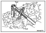
4. Remove valve collet, valve spring retainer and valve spring using Tool.
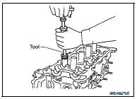
5. Remove valve oil seal using Tool.
Tool number : KV10107902 (J-38959)
INSTALLATION
1. Apply new engine oil to new valve oil seal joint surface and seal lip.
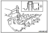
2. Press in valve oil seal to the position shown using Tool.
Oil seal installed height : 12.1 mm (0.476 in)
Tool number : KV10115600 (J-38958)
3. Installation of the remaining components is in the reverse order of removal.
Removal and Installation of Front Oil Seal
REMOVAL
1. Remove the following parts: • RH front wheel. Refer to WT-66, "Adjustment".
• Engine under cover using power tools.
• Drive belts. Refer to EM-16.
• Crankshaft pulley. Refer to EM-52.
2. Remove front oil seal from front cover.
CAUTION: Be careful not to scratch front cover.
INSTALLATION
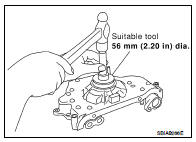
1. Install new front oil seal to front cover using suitable tool.
• Install new oil seal in until it is flush with front end surface of front cover.
CAUTION: • Do not reuse oil seal.
• Be careful not to cause damage to circumference of oil seal.
• Install new oil seal in the direction shown.
2. Installation of the remaining components is in the reverse order of removal.
Removal and Installation of Rear Oil Seal
REMOVAL
1. Remove the transaxle. Refer to TM-26, "Removal and Installation" (M/T), TM-259, "Removal and Installation" (CVT).
2. Remove flywheel (MT) or drive plate (CVT).
3. Remove rear oil seal using suitable tool.
CAUTION: Be careful not to scratch rear oil seal retainer.
• Install new oil seal in the direction shown.
• Press fit new oil seal straight using a suitable drift, to avoid causing burrs or tilting.
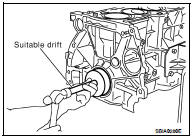
• Press in the new oil seal to the specified depth as shown.
2. Installation of the remaining components is in the reverse order of removal.
 Timing chain
 Cylinder head