Nissan Altima (L32) 2007-2012 Service Manual: Floor trim
Exploded View

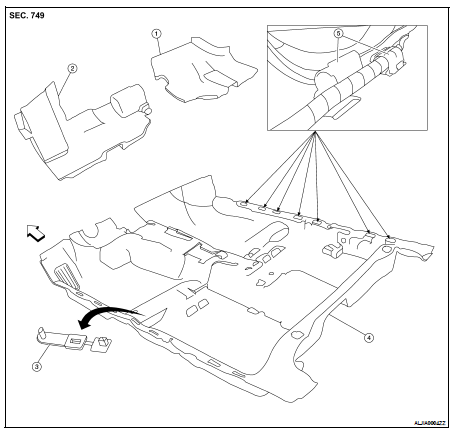
1. Spacer (RH)
2. Spacer (LH)
3. Floor mat hook
4. Floor carpet
5. Harness clamp

Removal and Installation
REMOVAL
1. Remove front seat (RH/LH) and rear seat cushion. Refer to SE-51, "Removal and Installation" and SE-53, "Removal and Installation".
2. Remove lower body side trim. Refer to INT-36, "Removal and Installation".
3. Remove center console. Refer to IP-12, "Removal and Installation".
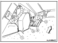
4. Remove the connector duct (RH/LH) (2) and the center connector duct (1) from heater and cooling unit. Refer to VTL-23, "DUCTS, NOZZLES AND GRILLES : Components".


5. Remove the bracket bolt, then position the parking brake cable aside.
6. Disconnect the drain hose (4) from the heater and cooling unit, then set aside.
7. Remove the three bolts (A) and one nut, then remove the bracket (3).
8. Remove the diagnosis sensor unit. Refer to PWO-5, "Removal and Installation".
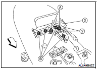
9. Remove the parking brake cable nuts (A), then position the parking brake cables (2) aside.


10. Remove the bracket nuts (B), then remove extension bracket (1) and center console rear bracket (3).
11. Remove front seat belt floor anchor bolt (RH/LH). Refer to SB-8, "Removal and Installation".
12. Release the tab, then remove floor mat hook.
13. Release the tabs and open harness clamps (seven-R/H and seven-L/H). Position harness and floor carpet cut-out areas outside of harness clamps.
14. Fold corners toward center, then remove floor carpet.
INSTALLATION
Installation is in the reverse order of removal.

 Rear parcel shelf finisher
 Headlining