Nissan Altima (L32) 2007-2012 Service Manual: Front stabilizer
Removal and Installation
REMOVAL
1. Remove steering gear. Refer to ST-17, "Removal and Installation".
2. Remove mounting nuts on upper portion of stabilizer connecting
rod.
3. Remove stabilizer clamp bolts.
4. Remove stabilizer from the vehicle.
INSPECTION AFTER REMOVAL
Check stabilizer, connecting rod, bushing and clamp for deformation, cracks
and damage, and replace if necessary.
INSTALLATION
Installation is in the reverse order of removal.
• Refer to FSU-12, "Exploded View" for tightening torque.
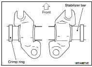
• When installing stabilizer, make sure that the clamps are facing in
the direction shown.
• Make sure the cut surface of the bushing faces the rear.
• Stabilizer uses pillow ball type connecting rod. Position ball joint
with case on pillow ball head parallel to stabilizer.
Removal and Installation
REMOVAL
1. Remove wheel and tire. Refer to WT-66, "Adjustment".
2. Remove steering knuckle from transverse link. Refer to FSU-12, "Exploded
View".
...
FRONT SUSPENSION ASSEMBLY
Exploded View
1. Strut tower bar
2. Stabilizer bar
3. Stabilizer clamp
4. Stabilizer bushing
5. Connecting rod
6. VQ35DE front mount bracket
7. VQ35DE rear mount ...
Other materials: Types of tires
WARNING
When changing or replacing tires, be
sure all four tires are of the same type
(i.e., Summer, All Season or Snow)
and construction. A NISSAN dealer
may be able to help you with information
about tire type, size, speed
rating and availability.
Replacement tires may have a lower
speed ...
Vehicle identification
Vehicle Identification Number (VIN)
plate
The Vehicle Identification Number (VIN)
plate is attached as shown. This number is
the identification for your vehicle and is
used in the vehicle registration.
Vehicle identification number
(chassis number)
The vehicle identification number is located
as s ...
Controls
Fan speed control dial
The fan speed control dial turns
the
fan on and off and controls fan speed.
Air flow control buttons
The air flow control buttons allow you to
select the air flow outlets.
- Air flows from center and side
vents.
- Air flows from center and side
vents and foot outlets.
- Air ...
 Transverse link
 Removal and installation