Nissan Altima (L32) 2007-2012 Service Manual: Transverse link
Removal and Installation
REMOVAL
1. Remove wheel and tire. Refer to WT-66, "Adjustment".
2. Remove steering knuckle from transverse link. Refer to FSU-12, "Exploded View".
3. Remove mounting nuts and washers on lower portion of stabilizer connecting rod.
4. Slightly loosen transverse link mounting bolts.
5. Remove transverse link bolts and nuts, and remove transverse link from suspension member.
INSPECTION AFTER REMOVAL
Visual Inspection
Check transverse link and bushing for deformation, cracks, and other damage. Replace the entire transverse link assembly if cracks, deformation or any other damage is found.
Ball Joint Inspection
CAUTION: Before measurement, move the ball joint at least ten times by hand to check for smooth movement.
Swing Torque Inspection
• Hook spring scale at cotter pin mounting hole. Confirm spring scale measurement value is within specifications when ball stud begins moving.
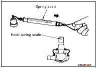
• If the value is outside the standard, replace transverse link.
Rotating Torque Inspection
• Attach nut to ball stud. Check that rotating torque is within specifications using Tool.
• If the value is outside the standard, replace transverse link.
Axial Endplay Inspect
• Move tip of ball joint in axial direction to check for looseness.
Axial endplay : 0.1 mm (0.004 in) or less
• If any looseness is noted, replace transverse link.
INSTALLATION
Installation is in the reverse order of removal.
• Refer to FSU-12, "Exploded View" for tightening torque.
• Tighten transverse link bolts with vehicle unladen and all four tires on flat, level ground.
• After installation, check wheel alignment. Refer to FSU-7, "Inspection and Adjustment".
 Front coil spring and strut
 Front stabilizer