Nissan Altima (L32) 2007-2012 Service Manual: Front timing chain case
Removal and Installation
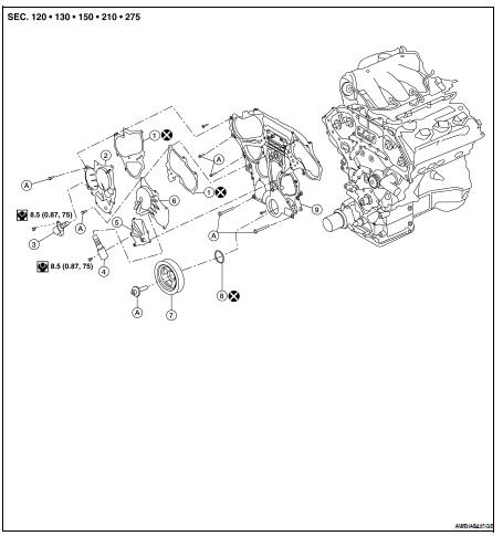
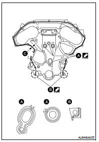
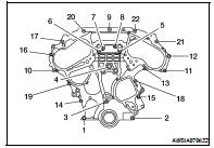
1. Gasket
2. IVT control valve cover RH
3. IVT valve RH
4. IVT valve LH
5. Water pump cover
6. IVT control valve cover LH
7. Crankshaft pulley
8. Front oil seal
9. Front timing chain case
A. Follow installation procedure
NOTE: • This section describes procedures for removal/installation procedure of the front timing chain case and timing chain related parts without removing the oil pan (upper) from the vehicle.
• When oil pan (upper) needs to be removed or installed, or when rear timing chain case is removed or installed, remove oil pans (upper and lower) first. Then remove front timing chain case, timing chain related parts, and rear timing chain case in this order, and install in reverse order of removal. Refer to EM-162.
• Refer to EM-162 for component parts location.
REMOVAL
1. Remove engine cover using power tool.
2. Release fuel pressure. Refer to EC-1579, "Inspection".
3. Remove the air cleaner case, mass air flow sensor and air cleaner to electric throttle control actuator tube.
Refer to EM-129, "Removal and Installation".
4. Remove the engine coolant reservoir. Refer to CO-38, "Removal and Installation".
5. Remove the cowl top and cowl top extension. Refer to EXT-18, "Removal and Installation".
6. Remove the IPDM E/R and position aside. Remove the bracket. Refer to PCS-48, "Removal and Installation".
7. Remove the front RH wheel and tire using power tool. Refer to WT-66, "Adjustment".
8. Remove the engine undercover.
9. Remove the RH inner fender splash shield.
10. Remove the drive belt, idler pulley and drive belt auto-tensioner. Refer to EM-121, "Removal and Installation" and EM-122, "Removal and Installation of Drive Belt Auto-tensioner".
11. Recover the A/C system R134a and remove the A/C compressor. Refer to HA-32, "HFC-134a (R-134a) Service Procedure".
12. Remove engine oil cooler pipe bolts.
13. Remove the power steering oil pump and reservoir tank with lines attached and position them aside. Refer to ST-20, "VQ35DE : Removal and Installation" 14. Remove the generator. Refer to CHG-27, "Removal and Installation".
15. Disconnect the engine harness and position aside.
16. Remove the A/C low-pressure flexible hose. Refer to HA-37, "Removal and Installation for Low-Pressure Flexible Hose".
17. Support the engine and remove the RH engine mounting insulator, mount and bracket. Refer to EM-202, "Removal and Installation".
18. Remove the water pump cover, using Tool.
Tool number : KV10111100 (J-37228)
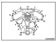
19. Remove the RH and LH IVT covers. Loosen the IVT cover bolts in the order as shown.
NOTE: The shaft in the cover is inserted into the center hole of the intake camshaft sprocket. Remove the cover by pulling straight out until the cover disengages from the camshaft sprocket.
20. Remove the starter motor. Refer to STR-51, "Removal and Installation".
21. Remove the intake manifold collector. Refer to EM-133, "Removal and Installation".
22. Remove the six ignition coils.
NOTE: Note locations for installation.
23. Remove the six spark plugs. Refer to EM-119, "Removal and Installation".
24. Remove the rocker covers as necessary. Refer to EM-151, "Removal and Installation LH" and EM-152, "Removal and Installation RH".
NOTE: Necessary only when removing secondary timing chains.
25. Obtain compression TDC of No. 1 cylinder as follows: a. Rotate crankshaft pulley clockwise to align timing mark (grooved line without color) with timing indicator.
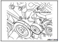
b. Check that intake and exhaust camshaft lobes on No. 1 cylinder (right bank of engine) are located as shown.
• If not, turn the crankshaft one revolution (360°) and align as shown.
26. Lock the drive plate (CVT), flywheel (M/T) using Tool attached to the starter bolt hole.
Tool number : KV10117700 (J-44716)
CAUTION: Do not damage the ring gear teeth, or the signal plate teeth behind the ring gear, when setting the Tool.
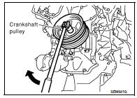
27. Remove the crankshaft pulley as follows: a. Loosen crankshaft pulley bolt using Tool and locate bolt seating surface at 10 mm (0.39 in) from its original position.
Tool number : KV10109300
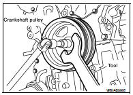
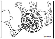
b. Position a pulley puller at recess hole of crankshaft pulley to remove crankshaft pulley.
CAUTION: Do not use a puller claw on crankshaft pulley periphery.
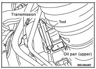
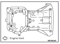
28. Loosen the lower oil pan bolts using power tool in order as shown. Remove the lower oil pan.
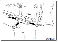
a. Insert Tool between the lower oil pan and the upper oil pan.
Tool number : KV10111100 (J37228)
• Be careful not to damage the mating surface.
• Do not insert a screwdriver, this will damage the mating surfaces.
b. Slide (2) the Tool by tapping (1) its side with a hammer to remove the lower oil pan from the upper oil pan.
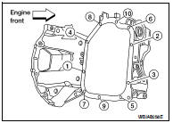
29. Remove upper oil pan bolts as shown.
30. Temporarily install lower oil pan.
31. Support front of engine with a suitable jack.
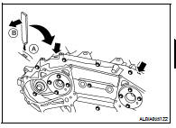
32. Remove the front timing chain case.
a. Loosen the front timing chain case bolts in the order as shown.
b. Insert the appropriate size tool into the notch (A) at the top of the front timing chain case as shown.
c. Pry off the case by moving the suitable tool (B) as shown.
• Cut liquid gasket for removal using Tool.
CAUTION: • Do not use a screwdriver or similar tool.
• After removal, handle carefully so it does not bend, or warp under a load.
33. Remove the front oil seal from the front timing chain case using a suitable tool.
CAUTION: Do not damage the front cover.
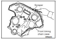
34. Use a scraper to remove all of the old Silicone RTV Sealant from the front timing chain case and opposite mating surfaces.
CAUTION: Do not damage the mating surfaces.
NSTALLATION
1. Install dowel pins (right and left) into front timing chain case up to a point close to taper in order to shorten protrusion length.
2. Install the new front oil seal on the front timing chain case. Apply new engine oil to the oil seal edges.
NOTE: Install it so that each seal lip is oriented as shown.
a. Install the new front oil seal so that it becomes flush with the face with front timing chain case using suitable drift.
CAUTION: Press fit straight and avoid causing burrs or tilting the oil seal.
NOTE: Make sure the garter spring is in position and seal lip is not inverted.
3. Apply Silicone RTV Sealant to front timing chain case as shown.
• Use Genuine Silicone RTV Sealant, or equivalent. Refer to GI- 15, "Recommended Chemical Products and Sealants".
• Before installation, wipe off the protruding sealant.
• C: 2.6 - 3.6 mm (0.102 - 0.142 in) dia.
4. Install dowel pin on the rear timing chain case into dowel pin hole in front timing chain case.
5. Loosely install the front timing chain case bolts.
6. Tighten the front timing chain case bolts in the order as shown.
• Retighten the front timing chain case bolts in the order as shown.
7. Remove lower oil pan.
8. Install upper oil pan bolts. Refer to EM-139, "Removal and Installation".
9. Install lower oil pan. Refer to EM-139, "Removal and Installation".
10. Install IVT control valve covers.
11. Apply liquid gasket and install the water pump cover.
• Use Genuine Silicone RTV Sealant or equivalent. Refer to GI-15, "Recommended Chemical Products and Sealants".
12. Install crankshaft pulley and tighten the bolt in two steps.
• Lubricate thread and seat surface of the bolt with new engine oil.
• Apply a paint mark for the second step of angle tightening.
13. Rotate crankshaft pulley in normal direction (clockwise when viewed from front) to confirm it turns smoothly.
14. Installation of the remaining components is in reverse order of removal.
 Rocker cover
 Timing chain