Nissan Altima (L32) 2007-2012 Service Manual: Timing chain
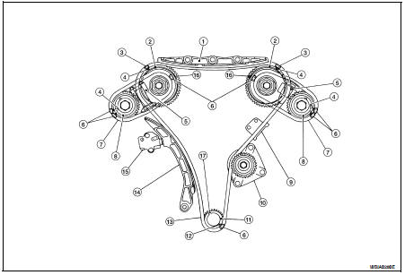
Component
1. Timing chain tensioner
2. Internal chain guide
3. Timing chain tensioner
4. Camshaft sprocket (EXH)
5. Timing chain (secondary)
6. Timing chain (primary)
7. Camshaft sprocket (INT)
8. Camshaft sprocket (INT)
9. Timing chain (secondary)
10. Camshaft sprocket (EXH)
11. Slack guide
12. Crankshaft sprocket
13. Rear timing chain case
14. Tension guide
15. O-ring
Refer to EM-111, "Precaution for Liquid Gasket".
• Before installation, wipe off any protruding sealant.
CAUTION: • After removing timing chain, do not turn the crankshaft and camshaft separately, or the valves will strike the pistons.
• When installing camshafts, chain tensioners, oil seals, or other sliding parts, lubricate contacting surfaces with new engine oil.
• Apply new engine oil to bolt threads and seat surfaces when installing camshaft sprockets, camshaft brackets, and crankshaft pulley.
• Before disconnecting fuel hose, release fuel pressure. Refer to EC-1579, "Inspection".
• Before removing the upper oil pan, remove the crankshaft position sensor (POS).
• Be careful not to damage sensor edges.
• Do not spill engine oil or coolant on drive belts.
Removal
1. Remove front timing chain cover. Refer to EM-155, "Removal and Installation".
2. Disconnect the power brake booster vacuum hose.
3. Disconnect the electric throttle control actuator.
4. Disconnect the coolant hoses at the electric throttle control actuator.
5. Disconnect the PCV hose.
6. Disconnect the EVAP canister purge volume control solenoid vacuum hose.
7. Remove the intake manifold collector. Refer to EM-130, "Removal and Installation".
8. Remove the six ignition coils.
9. Remove the six spark plugs. Refer to EM-119, "Removal and Installation".
10. Remove the engine oil dipstick.
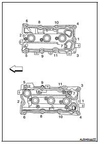
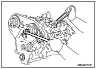
11. Remove the rocker covers. Loosen the bolts in the numerical order as shown.

12. Place paint marks on the timing chain and sprockets to indicate the correct position of the components for installation.
13. Remove the internal chain guide and slack guide.
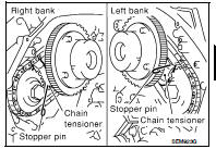
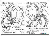
14. Remove the timing chain tensioner.
a. Pull lever down and release plunger stopper tab. Plunger stopper tab can be pushed up to release (coaxial structure with lever).
b. Insert stopper pin into tensioner body hole to hold lever, and keep the tab released. An Allen wrench [1.2 mm (0.047 in)] is used for a stopper pin as an example.
c. Insert plunger into tensioner body by pressing the slack side chain guide.
d. Keep the slack side chain guide pressed and hold it by pushing the stopper pin through the lever hole and body hole.
e. Remove the bolts and remove the timing chain tensioner.
15. Remove primary timing chain and crankshaft sprocket.
CAUTION: After removing timing chain, do not turn the crankshaft and camshaft separately, or the valves will strike the pistons.
16. Attach a suitable stopper pin to the right and left camshaft chain tensioners (for secondary timing chains).
17. Remove the intake and exhaust camshaft sprocket bolts.
• Apply paint to the timing chain and camshaft sprockets for alignment during installation.
• Secure the hexagonal portion of the camshaft using a wrench to loosen the bolts.
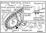
18. Remove the secondary timing chains with camshaft sprockets.
a. Rotate camshaft slightly, and slacken timing chain of timing chain tensioner -side.
b. Insert metal or resin plate [0.5 mm (0.020 in)] into guide between timing chain and chain tensioner plunger. Remove cam sprocket and secondary timing chain with timing chain removed from guide groove.
CAUTION: Chain tensioner plunger can move, while stopper pin is inserted in tensioner. Plunger can come out of tensioner when timing chain is removed. Use caution during removal.
• Intake camshaft sprocket is two-for-one structure of primary and secondary sprockets.
• Handle the intake sprockets as an assembly.
CAUTION: • Avoid impact or dropping the intake sprockets.
• Do not disassemble the intake sprockets (never loosen bolts (A) and (B) as shown).
19. Remove the chain tension guide.
20. Remove the rear timing chain case, if necessary. Refer to EM-173, "Removal and Installation".
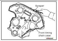
21. Use a scraper to remove all of the old Silicone RTV Sealant from the front timing chain case and opposite mating surfaces.
CAUTION: Do not damage the mating surfaces.
22. Remove all old Silicone RTV Sealant from all the bolt holes and bolts.
CAUTION: Do not damage the threads or mating surfaces.
23. Remove the front oil seal from the front timing chain case using a suitable tool.
CAUTION: Do not damage the front cover.
Inspection
Check for cracks and any excessive wear of the timing chain. Replace the timing chain as necessary.
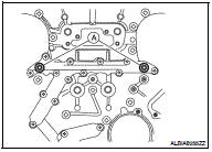
Installation
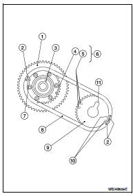
NOTE: The figure shows the relationship between the mating mark on each timing chain and that on the corresponding sprocket, the components installed.
1. Internal chain guide
2. Camshaft sprocket (intake)
3. Mating mark (pink link)
4. Mating mark (punched)
5. Secondary timing chain tensioner
6. Mating mark (orange link)
7. Secondary timing chain
8. Camshaft sprocket (exhaust)
9. Tension guide
10. Water pump
11. Crankshaft sprocket
12. Mating mark (notched)
13. Primary timing chain
14. Slack guide
15. Primary timing chain tensioner
16. Mating mark (back side)
17. Crankshaft key
1. Install the rear timing chain case, if removed. Refer to EM-173, "Removal and Installation".
2. Install the timing chain tension guide.
3. Position the crankshaft so No. 1 piston is set at TDC on the compression stroke.
• Make sure that the dowel pin hole, dowel pin and crankshaft key are located as shown.
Camshaft dowel pin hole (intake side): at cylinder head upper face side in each bank.
Camshaft dowel pin (exhaust side): at cylinder head upper face side in each bank.
Crankshaft key: at cylinder head side of RH bank.
CAUTION: Hole on small diameter side must be used for intake camshaft sprocket dowel pin. Do not misidentify (ignore big diameter side).
4. Install the secondary timing chains and camshaft sprockets.
CAUTION: Matching marks between the timing chain and sprockets slip easily. Confirm all matching mark positions repeatedly during the installation process.
• Push the sleeve of the secondary chain tensioner and keep it pressed in with a stopper pin.
a. Align the matching marks (4), (5), (7) and (10) on the secondary timing chain (8) (orange link) with the ones on the intake and exhaust sprockets (stamped), and install them.
• Matching marks for the intake sprocket are on the back side of the secondary sprocket.
• There are two types of matching marks, round (7) and (10) oval (4) and (5) types. They should be used for the RH and LH banks, respectively.
RH bank: use round type (7) and (10).
LH (6) bank: use oval type (4) and (5).
b. Align the dowel pin (3) with and pin hole on the camshaft sprocket INT side (1), and dowel pin groove (11) with the dowel pin on the camshaft EXH side, and install them.
• On the intake side, align the pin hole on the small diameter side of the camshaft front end with the dowel pin (3) on the back side of the camshaft sprocket (1), and install them.
• On the exhaust side, align the dowel pin on the camshaft front end with the dowel pin groove (11) on the camshaft sprocket (9), and install them.
• Camshaft sprocket bolts must be tightened in the next step.
Tightening them by hand is enough to prevent the dislocation of the dowel pins (3) and dowel pin grooves (11).
• It may be difficult to visually check the dislocation of mating marks during and after installation. To make the matching easier, make a mating mark on the sprocket teeth in advance with paint.
5. After confirming the mating marks are aligned, tighten the camshaft sprocket bolts.
• Secure the camshaft using a wrench at the hexagonal portion to tighten the bolts.

6. Pull the stopper pins out from the secondary timing chain tensioners.
7. Install the crankshaft sprocket on the crankshaft.
• Make sure the mating marks on the crankshaft sprocket face the front of the engine.
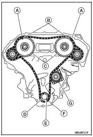
8. Install the primary timing chain.
• Install primary timing chain so the mating mark (punched) (B) on camshaft sprocket (C) is aligned with the pink link (A) on the timing chain, while the mating mark (notched) (E) on the crankshaft sprocket (D) is aligned with the orange one (F) on the timing chain, as shown.
• When it is difficult to align mating marks of the primary timing chain with each sprocket, gradually turn the camshaft using a wrench on the hexagonal portion to align it with the mating marks.
• During alignment, be careful to prevent dislocation of mating mark alignments of the secondary timing chains.
(G): Water pump
9. Install the internal chain guide and slack guide.
CAUTION: • Do not overtighten the slack guide bolts. It is normal for a gap to exist under the bolt seats when the bolts are tightened to specification.
10. Install the timing chain tensioner for the slack guide.
• When installing the chain tensioner, push in the sleeve and keep it pressed in with the stopper pin.
• Remove any dirt and foreign materials completely from the back and the mounting surfaces of the chain tensioner.
• After installation, pull out the stopper pin while pressing the slack guide.
11. Reconfirm that the matching marks on the sprockets and the timing chain have not slipped out of alignment.
12. Install new O-rings (A) on the rear timing chain case.
13. Install the front timing chain case. Refer to EM-155, "Removal and Installation".
14. Activate the fuel system. Check for any leaks when the system is repressurized and correct as necessary.
15. Start the engine and check all systems for leaks or improper operation. Correct as necessary.
• After starting engine, keep idling for three minutes. Then rev engine up to 3,000 rpm under no load to purge air from the high-pressure oil chamber of the chain tensioners. The engine may produce a rattling noise. This indicates that air still remains in the chamber and is not a matter of concern.
 Front timing chain case
 Rear timing chain case