Nissan Altima (L32) 2007-2012 Service Manual: Heater & cooling unit assembly
Removal and Installation
COMPONENTS
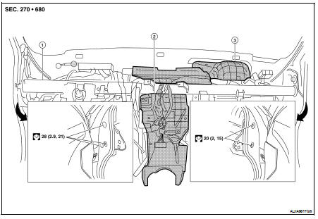
1. Steering member
2. Heater and cooling unit
3. Blower unit
REMOVAL
1. Discharge the refrigerant from the A/C system. Refer to HA-24, "HFC-134a (R-134a) Service Procedure".
2. Drain the engine coolant from the cooling system. Refer to CO-12, "Changing Engine Coolant" (QR25DE), CO-35, "Changing Engine Coolant" (VQ35DE).
3. Disconnect the negative battery terminal.
4. Remove the wiper motor and linkage. Refer to WW-116, "FRONT WIPER DRIVE ASSEMBLY : Removal and Installation".
5. Remove the upper cowl (for VQ35DE only). Refer to EXT-18, "Removal and Installation".
6. Remove the strut tower bar (for VQ35DE only). Refer to FSU-12, "Exploded View".
7. Remove the lower RH cowl (for VQ35DE only). Refer to EXT-18, "Removal and Installation".
8. Disconnect the heater hoses from the heater core pipes.
CAUTION: Cap or wrap the pipe joint with a suitable material such as vinyl tape to avoid the entry of contaminants into the system.
9. Disconnect the refrigerant lines from the expansion valve. Refer to HA-31, "Component".
CAUTION: Cap or wrap the line joint with a suitable material such as vinyl tape to avoid the entry of contaminants into the system.
10. Remove the instrument panel assembly. Refer to IP-12, "Removal and Installation".
11. Remove the steering column assembly. Refer to ST-14, "Removal and Installation".
12. Disconnect the drain hose.
13. Remove the heater and cooling unit assembly attached to the steering member as one assembly from the vehicle.
14. Remove the blower unit from the heater and cooling unit and steering member assembly.
15. Remove the heater and cooling unit from the steering member.
INSTALLATION
Installation is in the reverse order of removal.
• Fill the radiator with the specified water and coolant mixture. Refer to MA-12, "Fluids and Lubricants".
• Recharge the A/C system. Refer to HA-24, "HFC-134a (R-134a) Service Procedure".
 Intake sensor
 Blower unit