Nissan Altima (L32) 2007-2012 Service Manual: Hydraulic control system
System Diagram
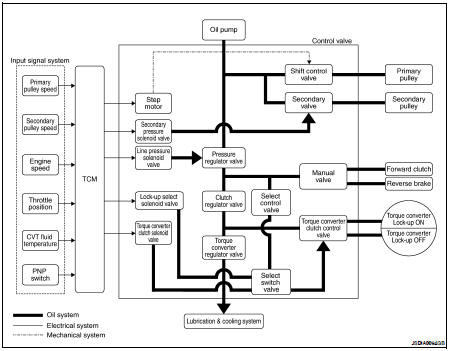
System Description
The hydraulic control mechanism consists of the oil pump directly driven by the engine, the hydraulic control valve that controls line pressure and transmission, and the input signal line.
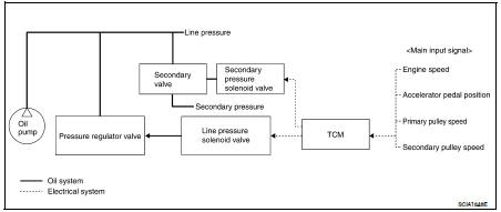
LINE PRESSURE AND SECONDARY PRESSURE CONTROL
• When an input torque signal equivalent to the engine drive force is sent from the ECM to the TCM, the TCM controls the line pressure solenoid valve and secondary pressure solenoid valve.
• This line pressure solenoid controls the pressure regulator valve as the signal pressure and adjusts the pressure of the operating oil discharged from the oil pump to the line pressure most appropriate to the driving state. Secondary pressure is controlled by decreasing line pressure.
Nomal Control
Optimize the line pressure and secondary pressure, depending on driving conditions, on the basis of the throttle position, the engine speed, the primary pulley (input) revolution speed, the secondary pulley (output) revolution speed, the brake signal, the PNP switch signal, the lock-up signal, the voltage, the target gear ratio, the fluid temperature, and the fluid pressure.
Feedback Control
When controlling the normal fluid pressure or the selected fluid pressure, the secondary pressure can be set more accurately by using the fluid pressure sensor to detect the secondary pressure and controlling the feedback.
Component Parts Location - Coupe
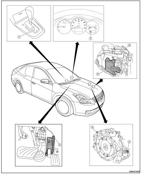
1. Control device assembly (Manual mode select switch and manual mode position select switch)
2. Accelerator pedal position (APP) sensor
3. Secondary speed sensor
4. CVT unit harness connector
5. TCM
6. Battery
7. Shift position indicator Manual mode indicator
Component Parts Location - Sedan
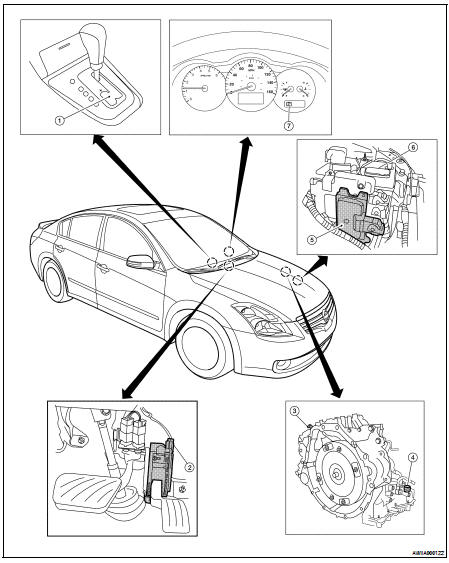
1. Control device assembly (Manual mode select switch and manual mode position select switch)
2. Accelerator pedal position (APP) sensor
3. Secondary speed sensor
4. CVT unit harness connector
5. TCM
6. Battery
7. Shift position indicator Manual mode indicator
Component Description
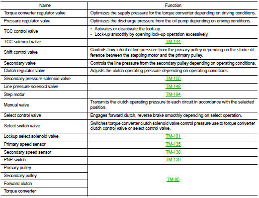
TRANSAXLE ASSEMBLY
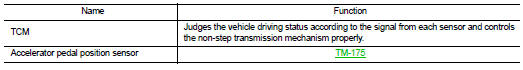
EXCEPT TRANSAXLE ASSEMBLY
 Mechanical system
 Control system