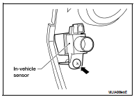
Nissan Altima (L32) 2007-2012 Service Manual: In-vehicle sensor
Removal and Installation
REMOVAL
1. Remove the instrument lower cover LH. Refer to IP-12, "Removal and
Installation".
2. Remove the in-vehicle sensor screw and remove the in-vehicle
sensor.
INSTALLATION
Installation is in the reverse order of removal.
• Make sure that the aspirator hose is securely attached to the in-vehicle
sensor when installing the instrument
lower cover LH.
Removal and Installation
FRONT AIR CONTROL
Removal
1. Remove cluster lid D. Refer to IP-12, "Removal and Installation".
2. Remove the two brackets (1) and remove the front air control ...
Removal and Installation
REMOVAL
1. Remove the front RH speaker grille (1). Refer to AV-73,
"Removal and Installation".
2. Disconnect the connector.
3. Release the sunload sensor ta ...
Other materials: Lane Departure Warning (LDW)
WARNING
Failure to follow the warnings and instructions
for proper use of the LDW
system could result in serious injury or
death.
This system is only a warning device
to inform the driver of a potential unintended
lane departure. It will not
steer the vehicle or prevent loss of
control. It is ...
Heated steering wheel switch (if so equipped)
Push the heated steering wheel switch to
warm the steering wheel after the ignition
switch is placed in the ON position. The
indicator light will come on.
If the surface temperature of the steering
wheel is below 68ºF (20ºC), the system will
heat the steering wheel and cycle off and
on to mainta ...
How to use the vehicle information
display
The vehicle information display can be
changed using the ,
, and OK buttons located on the
steering
wheel.
- Use these buttons
to navigate the vehicle information
display.
OK - Change or select an item in the
vehicle information display.
- Returns to the previous
menu.
The OK, and
butto ...


 Control unit
 Sunload sensor