Nissan Altima (L32) 2007-2012 Service Manual: Key cylinder switch
Description
For vehicles equipped with LH and RH anti-pinch system, the main power window and door lock/unlock switch detects condition of the door key cylinder switch and transmits to BCM as the LOCK or UNLOCK signal.
For vehicles equipped with LH anti-pinch system only, the door lock assembly LH (key cylinder switch) transmits the LOCK or UNLOCK signal directly to the BCM.
Component Function Check
1.CHECK DOOR KEY CYLINDER SWITCH INPUT SIGNAL
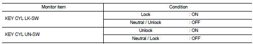
Check KEY CYL UN-SW, KEY CYL UN-SW in “DATA MONITOR” mode for “POWER DOOR LOCK SYSTEM” with CONSULT-III. Refer to DLK-276, "DOOR LOCK : CONSULT-III Function (BCM - DOOR LOCK)".
Is the inspection result normal? YES >> Key cylinder switch is OK.
NO >> With LH and RH anti-pinch, refer to SEC-116, "Diagnosis Procedure (With LH and RH Anti- Pinch)".
NO >> With LH anti-pinch only, refer to SEC-117, "Diagnosis Procedure (With LH Anti-Pinch Only)".
Diagnosis Procedure (With LH and RH Anti-Pinch)
1.CHECK DOOR KEY CYLINDER SWITCH INPUT SIGNAL
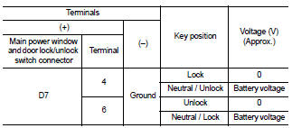
1. Turn ignition switch ON.
2. Check voltage between main power window and door lock/ unlock switch connector and ground.
Is the inspection result normal? YES >> Replace main power window and door lock/unlock switch. Refer to PWC-91, "Removal and Installation".
NO >> GO TO 2
2.CHECK DOOR KEY CYLINDER SIGNAL CIRCUIT
1. Turn ignition switch OFF.
2. Disconnect main power window and door lock/unlock switch connector and door lock assembly LH (key cylinder switch) connector.
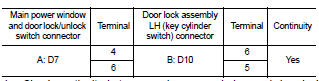
3. Check continuity between main power window and door lock/ unlock switch connector and door lock assembly LH (key cylinder switch) connector.
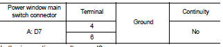
4. Check continuity between main power window and door lock/ unlock switch connector and ground.
Is the inspection result normal? YES >> GO TO 3
NO >> Repair or replace harness.
3.CHECK DOOR KEY CYLINDER SWITCH GROUND CIRCUIT
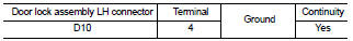
Check continuity between door lock assembly LH connector and ground.
Is the inspection result normal? YES >> GO TO 4
NO >> Repair or replace harness.
4.CHECK DOOR KEY CYLINDER SWITCH
Check door key cylinder switch.
Refer to SEC-118, "Component Inspection".
Is the inspection result normal? YES >> Check intermittent incident. Refer to GI-42, "Intermittent Incident".
NO >> Replace door lock assembly LH (key cylinder switch). Refer to DLK-222, "FRONT DOOR LOCK : Removal and Installation".
Diagnosis Procedure (With LH Anti-Pinch Only)
1.CHECK DOOR KEY CYLINDER SWITCH INPUT SIGNAL
1. Turn ignition switch ON.
2. Check voltage between BCM connector and ground.
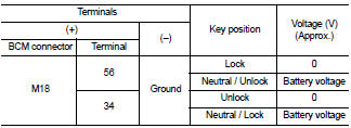
Is the inspection result normal? YES >> Replace main power window and door lock/unlock switch. Refer to PWC-91, "Removal and Installation".
NO >> GO TO 2
2.CHECK DOOR KEY CYLINDER SWITCH GROUND CIRCUIT
1. Turn ignition switch OFF.
2. Disconnect door lock assembly LH (key cylinder switch) connector.
3. Check continuity between door lock assembly LH (key cylinder switch) connector and ground.
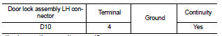
Is the inspection result normal? YES >> GO TO 3
NO >> Repair or replace harness.
3.CHECK DOOR KEY CYLINDER SIGNAL CIRCUIT
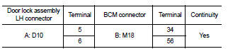
1. Disconnect BCM connector M18.
2. Check continuity between door lock assembly LH (key cylinder switch) connector D(10) terminals 5, 6 and BCM connector M18 (B) terminals 34, 56.
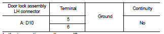
3. Check continuity between door lock assembly LH (key cylinder switch) connector D10 (A) terminals 5, 6 and ground.
Is the inspection result normal? YES >> GO TO 4
NO >> Repair or replace harness.
4.CHECK DOOR KEY CYLINDER SWITCH
Check door key cylinder switch.
Refer to SEC-118, "Component Inspection".
Is the inspection result normal? YES >> Check intermittent incident. Refer to GI-42, "Intermittent Incident".
NO >> Replace door lock assembly LH (key cylinder switch). Refer to DLK-222, "FRONT DOOR LOCK : Removal and Installation".
Component Inspection
1.CHECK DOOR KEY CYLINDER SWITCH
Check door lock assembly LH (key cylinder switch).
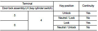
Is the inspection result normal? YES >> Key cylinder switch is OK.
NO >> Replace door lock assembly LH (key cylinder switch). Refer to DLK-222, "FRONT DOOR LOCK : Removal and Installation".
 Key slot illumination
 Horn
Horn